How to Use 12v DC 66 RPM L Redüktörlü Motor: Examples, Pinouts, and Specs
Introduction
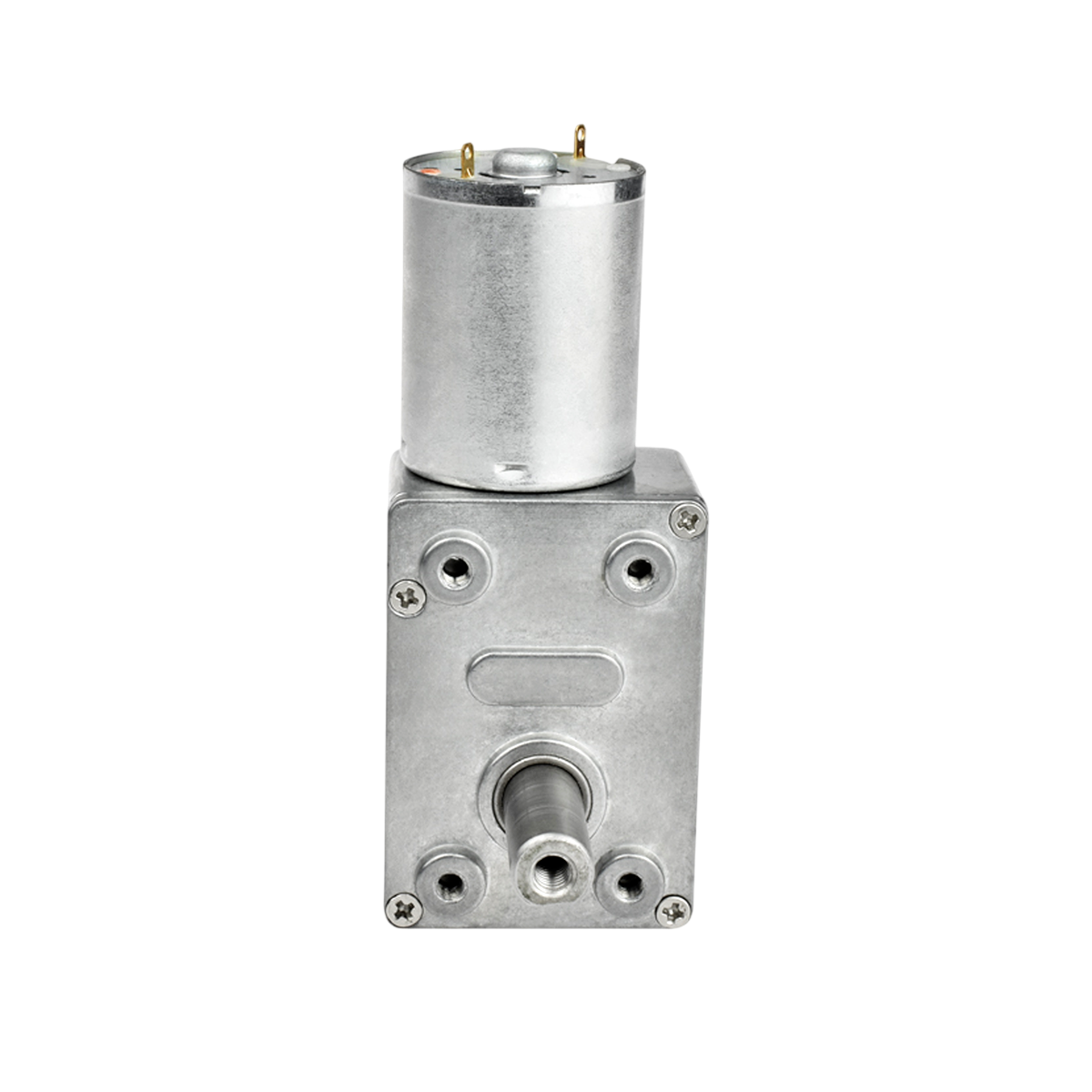
The 12V DC 66 RPM Gearbox Motor (JGY-370), manufactured by DRD, is a robust and reliable motor designed for applications requiring high torque and controlled rotational speed. This motor features a built-in gearbox (reduction mechanism) that reduces the speed to 66 RPM while significantly increasing torque. It is ideal for robotics, conveyor belts, automated systems, and other projects where precise movement and power are essential.
Explore Projects Built with 12v DC 66 RPM L Redüktörlü Motor


Explore Projects Built with 12v DC 66 RPM L Redüktörlü Motor
Common Applications
- Robotics (e.g., robotic arms, mobile robots)
- Conveyor systems
- Automated gates and doors
- DIY projects requiring controlled rotational motion
- Small-scale industrial machinery
Technical Specifications
Below are the key technical details of the JGY-370 motor:
| Parameter | Value |
|---|---|
| Operating Voltage | 12V DC |
| No-Load Speed | 66 RPM |
| Rated Torque | 10 kg·cm (approx.) |
| Gearbox Type | Reduction Gearbox |
| Shaft Diameter | 6 mm |
| Shaft Length | 15 mm |
| Motor Dimensions | 37 mm (diameter) x 57 mm (length) |
| Weight | ~200 g |
| Current Consumption | 200-300 mA (no load), up to 1.2 A (stall) |
| Direction Control | Reversible (by swapping polarity) |
Pin Configuration and Descriptions
The motor has two terminals for electrical connections:
| Pin | Description |
|---|---|
| + | Positive terminal (connect to +12V) |
| - | Negative terminal (connect to GND) |
Usage Instructions
How to Use the Motor in a Circuit
- Power Supply: Connect the motor to a 12V DC power source. Ensure the power supply can provide sufficient current (at least 1.5 A) to handle the motor's stall current.
- Polarity Control: To control the direction of rotation:
- Connect the positive terminal of the power supply to the motor's
+pin and the negative terminal to the-pin for clockwise rotation. - Reverse the connections to achieve counterclockwise rotation.
- Connect the positive terminal of the power supply to the motor's
- Speed Control: Use a Pulse Width Modulation (PWM) signal from a motor driver or microcontroller to control the motor's speed.
- Motor Driver: For microcontroller-based projects (e.g., Arduino), use an H-bridge motor driver (e.g., L298N or L293D) to safely control the motor's speed and direction.
Important Considerations
- Current Handling: Ensure your power supply and motor driver can handle the motor's stall current (1.2 A).
- Heat Dissipation: Prolonged operation at high torque may cause the motor to heat up. Allow adequate cooling time to prevent damage.
- Load Limitations: Avoid exceeding the rated torque (10 kg·cm) to prevent gearbox damage.
- Mounting: Secure the motor firmly to prevent vibrations or misalignment during operation.
Example: Connecting to an Arduino UNO
Below is an example of controlling the motor's speed and direction using an Arduino UNO and an L298N motor driver.
Circuit Connections
- Connect the motor's
+and-terminals to the L298N motor driver's output pins (e.g., OUT1 and OUT2). - Connect the L298N's
IN1andIN2pins to Arduino digital pins 8 and 9, respectively. - Connect the L298N's
ENApin to Arduino PWM pin 10 for speed control. - Provide a 12V power supply to the L298N's
VCCpin and connect itsGNDto the Arduino's GND.
Arduino Code
// Define motor control pins
const int IN1 = 8;  // Motor direction control pin 1
const int IN2 = 9;  // Motor direction control pin 2
const int ENA = 10; // Motor speed control (PWM)

// Setup function
void setup() {
  pinMode(IN1, OUTPUT); // Set IN1 as output
  pinMode(IN2, OUTPUT); // Set IN2 as output
  pinMode(ENA, OUTPUT); // Set ENA as output
}

// Loop function
void loop() {
  // Rotate motor clockwise at 50% speed
  digitalWrite(IN1, HIGH);  // Set IN1 HIGH
  digitalWrite(IN2, LOW);   // Set IN2 LOW
  analogWrite(ENA, 128);    // Set PWM duty cycle to 50% (128/255)

  delay(3000); // Run for 3 seconds

  // Rotate motor counterclockwise at full speed
  digitalWrite(IN1, LOW);   // Set IN1 LOW
  digitalWrite(IN2, HIGH);  // Set IN2 HIGH
  analogWrite(ENA, 255);    // Set PWM duty cycle to 100% (255/255)

  delay(3000); // Run for 3 seconds

  // Stop the motor
  digitalWrite(IN1, LOW);   // Set IN1 LOW
  digitalWrite(IN2, LOW);   // Set IN2 LOW
  analogWrite(ENA, 0);      // Set PWM duty cycle to 0% (stop)

  delay(3000); // Wait for 3 seconds before repeating
}
Troubleshooting and FAQs
Common Issues
Motor Does Not Rotate
- Cause: Insufficient power supply or loose connections.
- Solution: Verify the power supply voltage and current. Check all connections.
Motor Heats Up Excessively
- Cause: Prolonged operation at high torque or stall conditions.
- Solution: Reduce the load on the motor and allow cooling periods.
Motor Rotates in the Wrong Direction
- Cause: Incorrect polarity of connections.
- Solution: Swap the
+and-connections to reverse the direction.
Noisy Operation
- Cause: Loose mounting or worn-out gearbox.
- Solution: Secure the motor properly and inspect the gearbox for wear.
FAQs
Can I use a lower voltage (e.g., 6V) to power the motor?
- Yes, but the motor's speed and torque will decrease proportionally.
Is the motor waterproof?
- No, the motor is not waterproof. Avoid exposing it to water or moisture.
Can I control the motor without a motor driver?
- Yes, but it is not recommended. A motor driver provides safer and more efficient control, especially for speed and direction.
What is the maximum load the motor can handle?
- The motor is rated for a maximum torque of 10 kg·cm. Exceeding this limit may damage the gearbox.