How to Use LilyPad_Coin_Cell_Battery_Holder-Switched-20mm: Examples, Pinouts, and Specs
Introduction
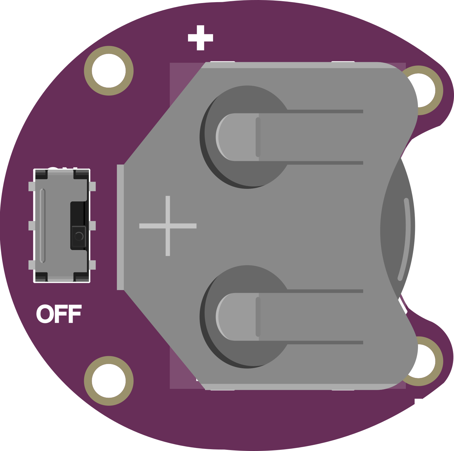
The LilyPad Coin Cell Battery Holder - Switched - 20mm is a compact, sewable power supply module designed for use with LilyPad Arduino boards and other wearable electronics. This holder is specifically tailored to hold a 20mm coin cell battery, providing a convenient and discreet power source for your projects. The integrated on/off switch allows for easy power management without the need to disconnect the battery, making it ideal for wearable applications where space and convenience are paramount.
Explore Projects Built with LilyPad_Coin_Cell_Battery_Holder-Switched-20mm
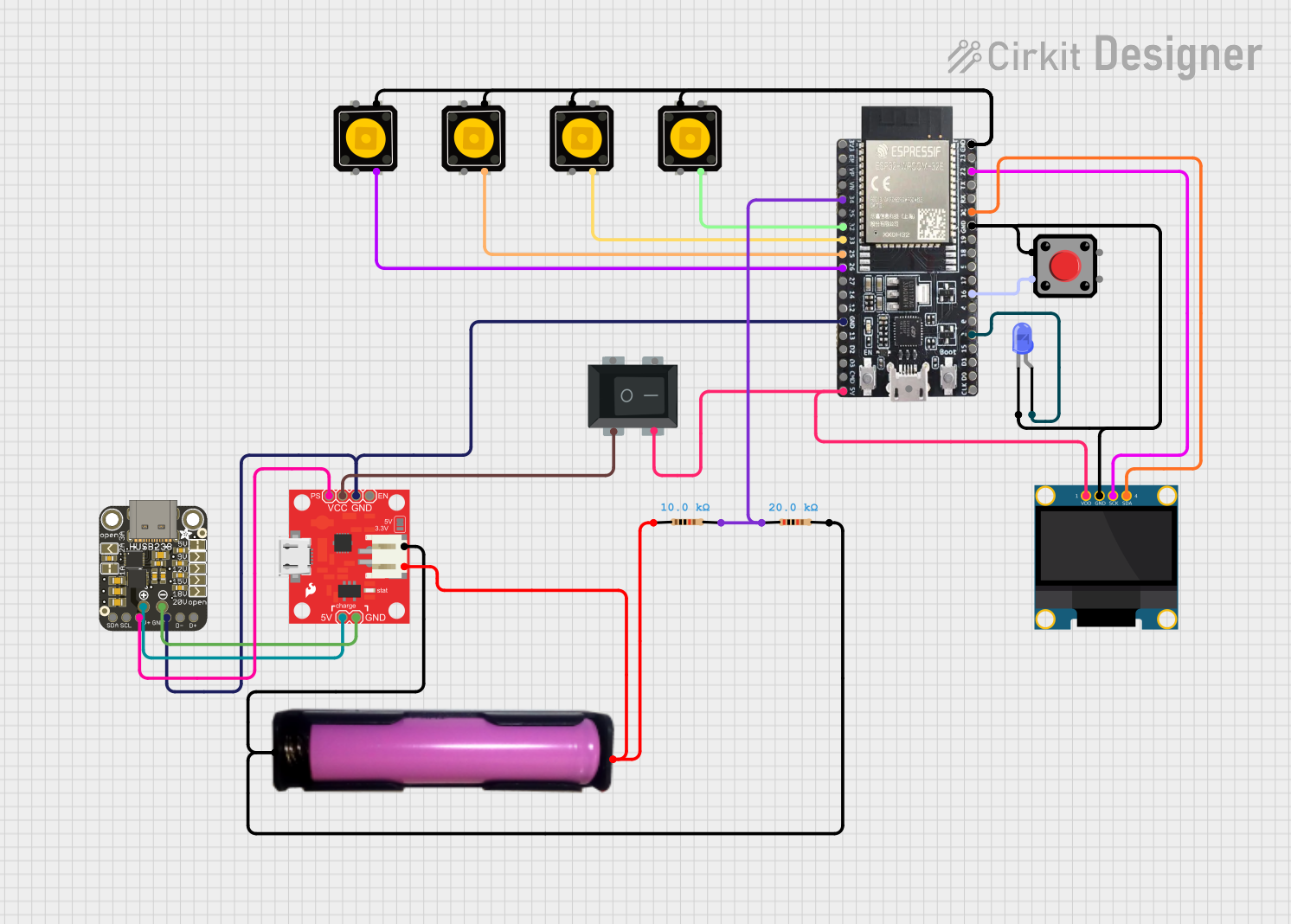

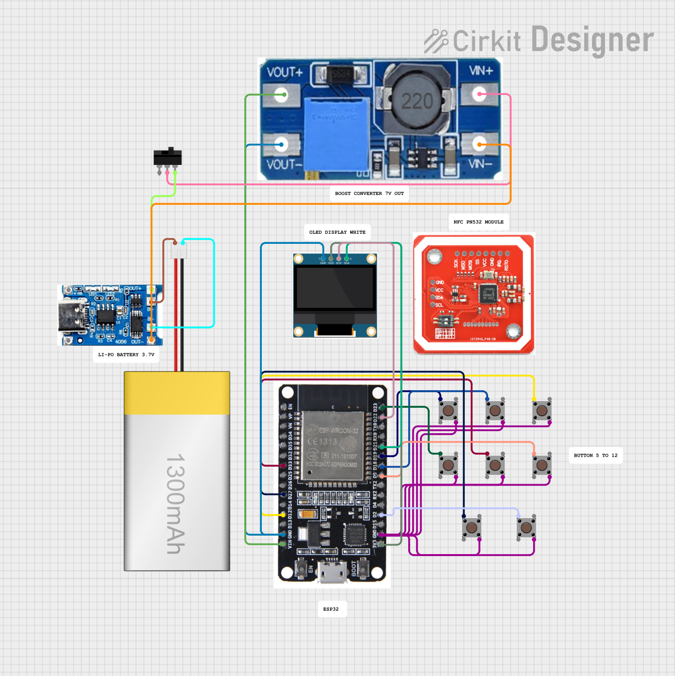

Explore Projects Built with LilyPad_Coin_Cell_Battery_Holder-Switched-20mm
Common Applications and Use Cases
- Wearable electronics
- E-textiles and smart garments
- Small, portable Arduino projects
- Educational projects and workshops
- Prototyping for fashion technology
Technical Specifications
Key Technical Details
- Voltage: 3V (typical for a CR2032 coin cell battery)
- Current: Maximum supply current depends on the coin cell battery used
- Battery Type: CR2032 or equivalent 20mm coin cell battery
- Dimensions: Approximately 23mm diameter
- Weight: Less than 5 grams (without battery)
Pin Configuration and Descriptions
| Pin Label | Description |
|---|---|
+ |
Positive connection to the coin cell |
- |
Negative connection to the coin cell |
S |
Connected to the switch (output to load) |
Usage Instructions
How to Use the Component in a Circuit
Inserting the Battery:
- Place a CR2032 coin cell battery into the holder with the positive side facing up.
Connecting to a LilyPad Arduino:
- Sew or connect the positive (
+) pad of the battery holder to the+power input on the LilyPad Arduino. - Sew or connect the negative (
-) pad to the-ground on the LilyPad Arduino. - Use conductive thread or wires for making connections if sewing.
- Sew or connect the positive (
Powering On/Off:
- Slide the switch to the ON position to power the connected device.
- Slide the switch to the OFF position to disconnect power.
Important Considerations and Best Practices
- Battery Life: Coin cell batteries have limited capacity. Use power-saving techniques in your design to extend battery life.
- Switch Handling: Be gentle with the switch to avoid damage.
- Short Circuits: Ensure there are no short circuits in your sewn connections.
- Storage: Remove the battery when not in use to prevent slow discharge.
Troubleshooting and FAQs
Common Issues
Device Not Powering On:
- Check if the battery is inserted correctly with the positive side up.
- Ensure the switch is in the ON position.
- Verify that the battery has charge and is not depleted.
Intermittent Power:
- Inspect sewn connections for loose threads or breaks.
- Confirm that the battery holder contacts are clean and making good contact with the battery.
Solutions and Tips for Troubleshooting
- Battery Replacement: If the device is not powering on and the connections are secure, try replacing the battery with a new one.
- Connection Maintenance: Regularly check and reinforce sewn connections to prevent wear and tear.
- Contact Cleaning: Clean the battery holder contacts with a dry cloth if they become dirty or tarnished.
FAQs
Q: Can I use a battery other than CR2032?
- A: The holder is designed for 20mm coin cell batteries. Using other sizes or types may result in poor contact or fit.
Q: How long will the battery last?
- A: Battery life depends on the capacity of the coin cell and the current draw of your project. CR2032 batteries typically have a capacity of around 220mAh.
Q: Is the battery holder washable?
- A: The battery holder is not waterproof. Remove the battery and ensure the holder is completely dry before washing.
Example Code for Arduino UNO
// Example code to blink an LED using a LilyPad Arduino powered by the Coin Cell Battery Holder

const int LED_PIN = 13; // The pin number for the LED

void setup() {
  pinMode(LED_PIN, OUTPUT); // Set the LED pin as an output
}

void loop() {
  digitalWrite(LED_PIN, HIGH); // Turn on the LED
  delay(1000);                // Wait for 1 second
  digitalWrite(LED_PIN, LOW);  // Turn off the LED
  delay(1000);                // Wait for 1 second
}
Note: This example assumes you have an LED connected to pin 13 and ground on the LilyPad Arduino, powered by the LilyPad Coin Cell Battery Holder. Adjust the pin number as necessary for your specific setup.