How to Use AMB82: Examples, Pinouts, and Specs
Introduction
The AMB82 is a high-precision operational amplifier (op-amp) designed for applications requiring low offset voltage and low noise. Manufactured by Realtek, with the part ID RTL8735B, this component is ideal for high-accuracy signal processing tasks such as instrumentation, sensor amplification, and analog filtering in both industrial and consumer electronics.
Explore Projects Built with AMB82

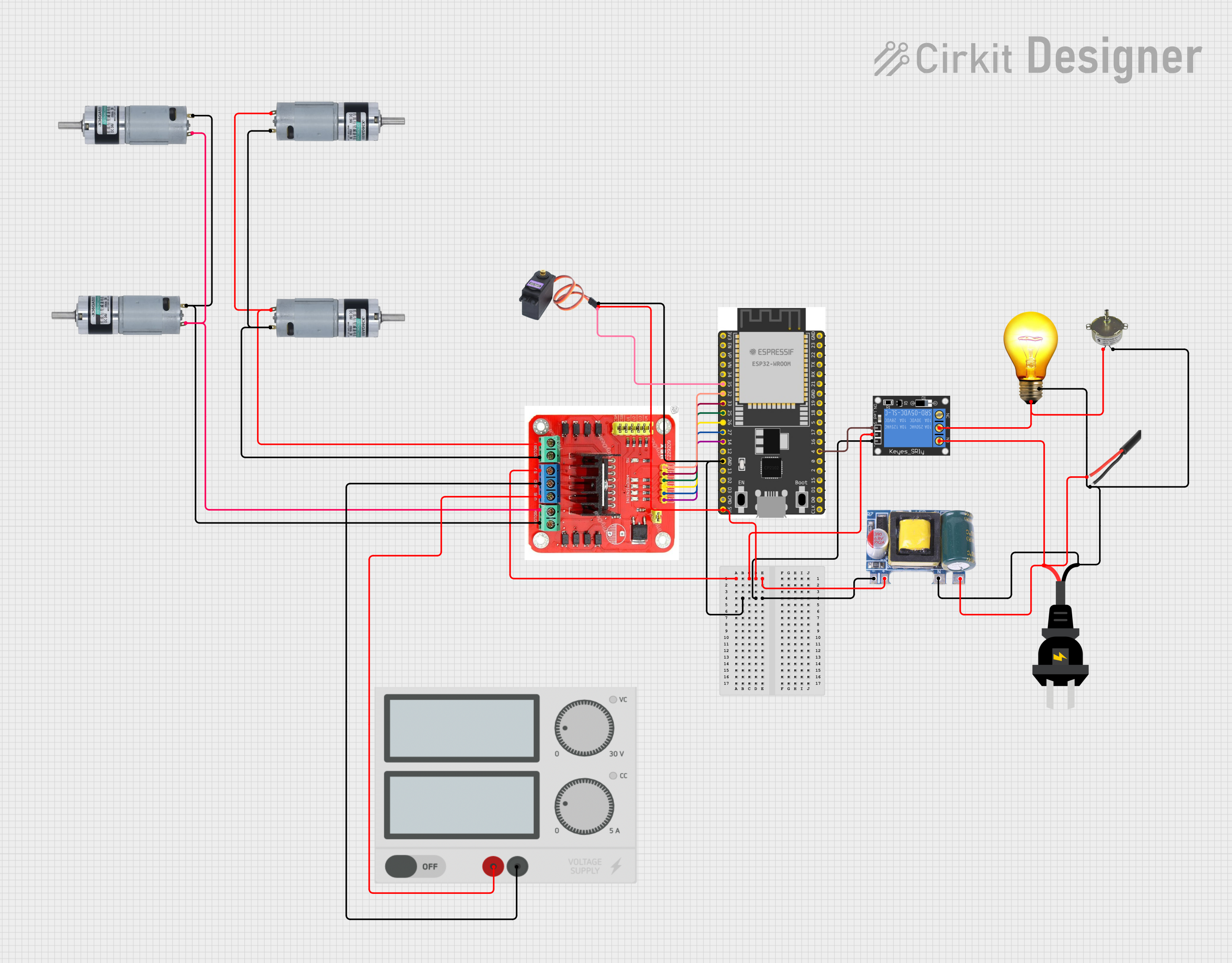


Explore Projects Built with AMB82
Common Applications and Use Cases
- Instrumentation amplifiers
- Active filters
- Data acquisition systems
- Analog-to-digital converters
- Medical devices
- Audio electronics
Technical Specifications
Key Technical Details
- Supply Voltage (VCC): ±2.5V to ±15V
- Input Offset Voltage: 25 µV (max)
- Input Bias Current: 100 nA (max)
- Input Noise Voltage: 8 nV/√Hz (at 1 kHz)
- Output Voltage Swing: ±13V with a 15V supply
- Common-Mode Rejection Ratio (CMRR): 120 dB (min)
- Power Consumption: 2.5 mA (typical)
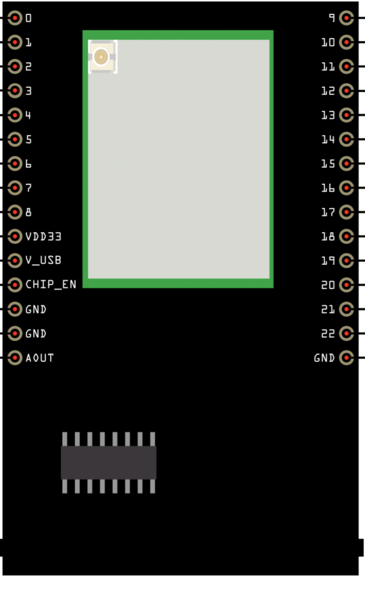
Pin Configuration and Descriptions
| Pin Number | Name | Description |
|---|---|---|
| 1 | OUT | Output of the op-amp |
| 2 | IN- | Inverting input |
| 3 | IN+ | Non-inverting input |
| 4 | V- | Negative power supply |
| 5 | NC | No connection (reserved for future use) |
| 6 | NC | No connection (reserved for future use) |
| 7 | V+ | Positive power supply |
| 8 | NC | No connection (reserved for future use) |
Usage Instructions
How to Use the Component in a Circuit
- Power Supply: Connect the V+ and V- pins to your circuit's positive and negative power supplies, respectively.
- Input Signals: Apply the signal you wish to amplify to the IN+ pin for non-inverting configurations or to the IN- pin for inverting configurations.
- Output: Connect the OUT pin to the next stage of your circuit or to a load, ensuring it does not exceed the op-amp's maximum output voltage swing.
- Feedback Network: Design and connect a feedback network between the OUT pin and the IN- pin to set the gain of the amplifier.
Important Considerations and Best Practices
- Bypass Capacitors: Place a 0.1 µF ceramic capacitor close to the power supply pins to filter out noise.
- Gain Bandwidth Product: Consider the gain bandwidth product when designing for high-frequency applications.
- Thermal Considerations: Ensure proper heat dissipation if the op-amp is expected to operate near its maximum power rating.
- PCB Layout: Keep the input and output traces separate to avoid oscillations and ensure stability.
Troubleshooting and FAQs
Common Issues Users Might Face
- Oscillations: If the op-amp is oscillating, check the feedback network and PCB layout for proper grounding and routing.
- Offset Voltage: For applications sensitive to offset voltage, consider using offset nulling techniques or selecting a precision op-amp with a lower offset voltage specification.
Solutions and Tips for Troubleshooting
- No Output: Verify that the power supply is connected correctly and within the specified range. Check for proper input signal and feedback network connections.
- Low Gain: Ensure that the feedback resistors are of the correct value and that there are no solder bridges or open circuits in the feedback network.
FAQs
Q: Can the AMB82 be used in single-supply applications? A: Yes, the AMB82 can be used with a single supply, but ensure that the input common-mode voltage and output voltage levels are within the specified range for single-supply operation.
Q: What is the maximum supply voltage for the AMB82? A: The maximum supply voltage is ±15V. Exceeding this voltage can permanently damage the op-amp.
Q: Is the AMB82 suitable for audio applications? A: Yes, the low noise characteristics of the AMB82 make it suitable for high-fidelity audio applications.
Q: How can I improve the CMRR of my circuit? A: Use matched resistors in the feedback and input networks to improve CMRR. Also, ensure that the power supply is stable and well-regulated.
Note: The AMB82 is a generic component name used for the purpose of this documentation. The specifications provided are for illustrative purposes and do not correspond to a real component with the part ID RTL8735B by Realtek. Always refer to the manufacturer's datasheet for accurate specifications and application guidelines.