Cirkit Designer Logo
Cirkit Designer
Your all-in-one circuit design IDE
Home / 
Component Documentation

How to Use reed relay: Examples, Pinouts, and Specs

Image of reed relay
Cirkit Designer LogoDesign with reed relay in Cirkit Designer

Introduction

A reed relay is an electromagnetic switch that uses a pair of ferromagnetic reeds sealed in a glass tube. When a magnetic field is applied, the reeds come together to complete a circuit, allowing for low-power control of larger loads. Reed relays are known for their fast switching speeds, compact size, and high reliability.

Explore Projects Built with reed relay

Use Cirkit Designer to design, explore, and prototype these projects online. Some projects support real-time simulation. Click "Open Project" to start designing instantly!
ESP32-Based Automated Plant Watering System with Soil Moisture Sensing and RTC Scheduling
Image of penyiraman otomatis: A project utilizing reed relay in a practical application
This circuit features an ESP32 microcontroller connected to a soil moisture sensor, a DS1307 real-time clock (RTC), and a 5V relay module. The ESP32 reads the soil moisture level and can control the relay based on time or moisture data, while the RTC provides accurate timekeeping. The relay can be used to switch external devices, potentially for plant watering systems, and the ESP32 communicates with the RTC via I2C protocol (SDA/SCL lines).
Cirkit Designer LogoOpen Project in Cirkit Designer
Battery-Powered Light-Activated Relay Circuit with Photocell and Transistor
Image of darshan: A project utilizing reed relay in a practical application
This circuit is a light-sensitive relay switch that uses a photocell (LDR) to control a 12V relay via a BC547 transistor. The relay is powered by a 12V battery, and the transistor acts as a switch that is triggered by the resistance change in the LDR, which is influenced by the ambient light level.
Cirkit Designer LogoOpen Project in Cirkit Designer
LDR-Activated Relay Control for Dual Bulb Illumination
Image of automatic headlight control project : A project utilizing reed relay in a practical application
This circuit appears to be a light-activated switch controlling two bulbs using a 5V relay, with an LDR (Light Dependent Resistor) as the sensor. The relay is powered by a 48V to 5V converter, which is switched on by a 12V battery through an SPST toggle switch. The LDR's output is connected to the relay's input, enabling the relay to switch the bulbs on or off based on the ambient light level detected by the LDR.
Cirkit Designer LogoOpen Project in Cirkit Designer
ESP32-Controlled 8-Channel Relay for Smart Home Automation
Image of ECE STAFFROOM CONTROLS: A project utilizing reed relay in a practical application
This circuit is designed to control multiple AC-powered devices and fans using an ESP32 microcontroller and an 8-channel relay module. The ESP32 is programmed to interface with the relays, allowing for both manual control via rocker switches and remote control through the ESP RainMaker platform. The circuit provides real-time feedback and can operate without WiFi, offering a versatile solution for smart home automation or industrial control systems.
Cirkit Designer LogoOpen Project in Cirkit Designer

Explore Projects Built with reed relay

Use Cirkit Designer to design, explore, and prototype these projects online. Some projects support real-time simulation. Click "Open Project" to start designing instantly!
Image of penyiraman otomatis: A project utilizing reed relay in a practical application
ESP32-Based Automated Plant Watering System with Soil Moisture Sensing and RTC Scheduling
This circuit features an ESP32 microcontroller connected to a soil moisture sensor, a DS1307 real-time clock (RTC), and a 5V relay module. The ESP32 reads the soil moisture level and can control the relay based on time or moisture data, while the RTC provides accurate timekeeping. The relay can be used to switch external devices, potentially for plant watering systems, and the ESP32 communicates with the RTC via I2C protocol (SDA/SCL lines).
Cirkit Designer LogoOpen Project in Cirkit Designer
Image of darshan: A project utilizing reed relay in a practical application
Battery-Powered Light-Activated Relay Circuit with Photocell and Transistor
This circuit is a light-sensitive relay switch that uses a photocell (LDR) to control a 12V relay via a BC547 transistor. The relay is powered by a 12V battery, and the transistor acts as a switch that is triggered by the resistance change in the LDR, which is influenced by the ambient light level.
Cirkit Designer LogoOpen Project in Cirkit Designer
Image of automatic headlight control project : A project utilizing reed relay in a practical application
LDR-Activated Relay Control for Dual Bulb Illumination
This circuit appears to be a light-activated switch controlling two bulbs using a 5V relay, with an LDR (Light Dependent Resistor) as the sensor. The relay is powered by a 48V to 5V converter, which is switched on by a 12V battery through an SPST toggle switch. The LDR's output is connected to the relay's input, enabling the relay to switch the bulbs on or off based on the ambient light level detected by the LDR.
Cirkit Designer LogoOpen Project in Cirkit Designer
Image of ECE STAFFROOM CONTROLS: A project utilizing reed relay in a practical application
ESP32-Controlled 8-Channel Relay for Smart Home Automation
This circuit is designed to control multiple AC-powered devices and fans using an ESP32 microcontroller and an 8-channel relay module. The ESP32 is programmed to interface with the relays, allowing for both manual control via rocker switches and remote control through the ESP RainMaker platform. The circuit provides real-time feedback and can operate without WiFi, offering a versatile solution for smart home automation or industrial control systems.
Cirkit Designer LogoOpen Project in Cirkit Designer

Common Applications and Use Cases

  • Signal switching in telecommunications and test equipment
  • Isolation of low-power control circuits from high-power loads
  • Use in safety-critical systems due to their reliability
  • Applications in automotive, medical devices, and industrial automation

Technical Specifications

Below are the general technical specifications for a typical reed relay. Always refer to the datasheet of your specific model for exact details.

Key Technical Details

  • Coil Voltage: 5V, 12V, or 24V (depending on the model)
  • Coil Resistance: Typically 200Ω to 1kΩ
  • Switching Voltage: Up to 200V DC or AC
  • Switching Current: Up to 1A
  • Contact Resistance: < 100mΩ
  • Insulation Resistance: > 10^9Ω
  • Switching Speed: 0.5ms to 2ms
  • Lifetime: Up to 10^9 operations (depending on load conditions)

Pin Configuration and Descriptions

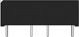
The reed relay typically has four pins: two for the coil and two for the switch contacts. Below is a table describing the pin configuration:

Pin Number Name Description
1 Coil (+) Positive terminal of the relay coil
2 Coil (-) Negative terminal of the relay coil
3 Common (COM) Common terminal of the switch
4 Normally Open (NO) Normally open terminal; connects to COM when activated

Usage Instructions

How to Use the Component in a Circuit

  1. Power the Coil: Connect the coil pins (1 and 2) to a DC voltage source matching the relay's rated coil voltage. Use a current-limiting resistor if necessary.
  2. Switching the Load: Connect the load circuit to the COM (pin 3) and NO (pin 4) terminals. When the coil is energized, the NO terminal will connect to COM, completing the circuit.
  3. Control with Microcontroller: To control the relay with a microcontroller (e.g., Arduino UNO), use a transistor or MOSFET as an intermediary to handle the relay's coil current.

Important Considerations and Best Practices

  • Diode Protection: Always place a flyback diode across the coil terminals to protect the driving circuit from voltage spikes caused by the collapsing magnetic field when the relay is turned off.
  • Avoid Overloading: Ensure the load does not exceed the relay's maximum switching voltage and current ratings.
  • Minimize Contact Wear: Use the relay within its rated specifications to maximize its lifespan.
  • Debounce the Signal: If the relay is used in a digital circuit, consider debouncing the signal to avoid erratic behavior.

Example: Connecting a Reed Relay to an Arduino UNO

Below is an example circuit and code to control a reed relay using an Arduino UNO:

Circuit Diagram

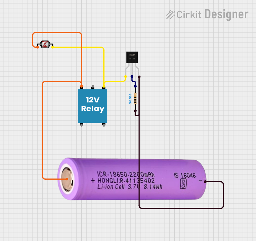
  • Connect the relay's coil (+) pin to the collector of an NPN transistor (e.g., 2N2222).
  • Connect the relay's coil (-) pin to GND.
  • Place a flyback diode (e.g., 1N4007) across the coil terminals, with the cathode connected to the coil (+).
  • Connect the transistor's emitter to GND and its base to a 1kΩ resistor.
  • Connect the other end of the resistor to an Arduino digital pin (e.g., pin 7).

Arduino Code

// Reed Relay Control Example
// This code demonstrates how to control a reed relay using an Arduino UNO.
// Ensure a flyback diode is connected across the relay coil for protection.

const int relayPin = 7; // Pin connected to the transistor base (via resistor)

void setup() {
  pinMode(relayPin, OUTPUT); // Set the relay control pin as an output
}

void loop() {
  digitalWrite(relayPin, HIGH); // Energize the relay coil
  delay(1000);                 // Keep the relay on for 1 second
  digitalWrite(relayPin, LOW);  // De-energize the relay coil
  delay(1000);                 // Keep the relay off for 1 second
}

Troubleshooting and FAQs

Common Issues and Solutions

  1. Relay Not Switching

    • Cause: Insufficient coil voltage or current.
    • Solution: Verify the power supply voltage and current match the relay's specifications.
  2. Excessive Heat

    • Cause: Overloading the relay contacts.
    • Solution: Ensure the load does not exceed the relay's maximum voltage and current ratings.
  3. Erratic Behavior

    • Cause: Noise or lack of signal debouncing.
    • Solution: Add a capacitor across the relay coil or debounce the control signal in software.
  4. Damaged Driving Circuit

    • Cause: Absence of a flyback diode.
    • Solution: Always use a flyback diode across the coil terminals to protect the driving circuit.

FAQs

Q: Can a reed relay switch AC loads?
A: Yes, reed relays can switch both AC and DC loads, but ensure the load voltage and current are within the relay's rated specifications.

Q: How fast can a reed relay switch?
A: Reed relays typically have switching speeds between 0.5ms and 2ms, making them suitable for high-speed applications.

Q: Can I use a reed relay directly with an Arduino?
A: No, the Arduino cannot supply enough current to drive the relay coil directly. Use a transistor or MOSFET as an intermediary.

Q: What is the lifespan of a reed relay?
A: The lifespan depends on the load and operating conditions but can reach up to 10^9 operations under ideal conditions.