How to Use N-MOSFET: Examples, Pinouts, and Specs
Introduction
An N-channel Metal-Oxide-Semiconductor Field-Effect Transistor (N-MOSFET) is a type of transistor that uses an n-type semiconductor for the channel. It is widely used in electronic circuits for switching and amplifying signals. The N-MOSFET operates by allowing current to flow from the drain to the source when a positive voltage is applied to the gate terminal, making it a key component in digital and analog circuits.
Explore Projects Built with N-MOSFET

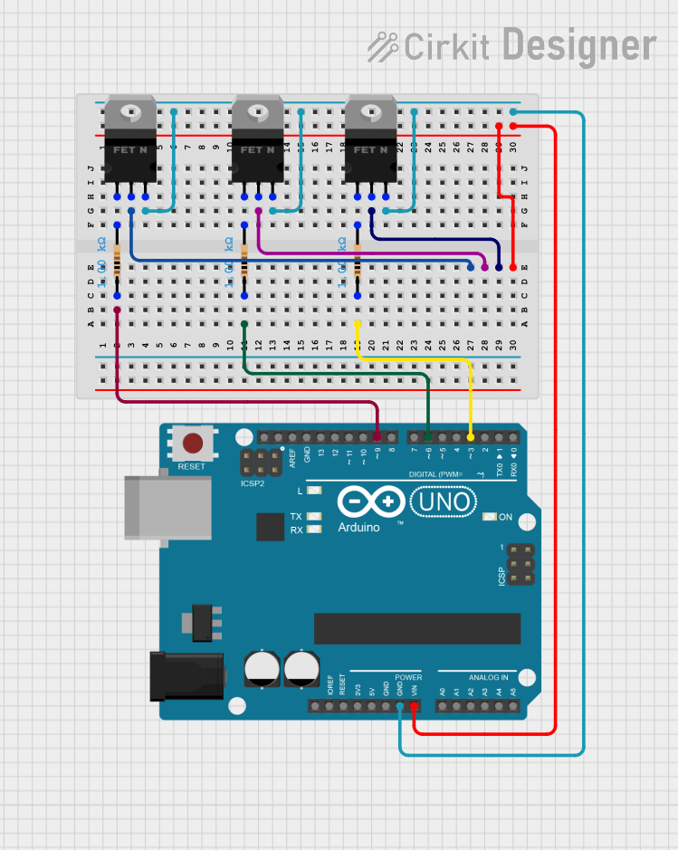

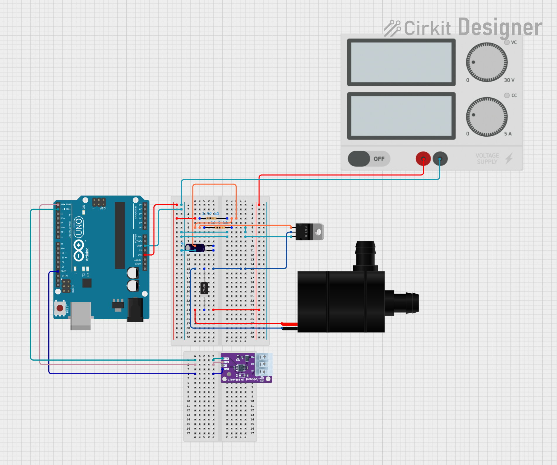
Explore Projects Built with N-MOSFET
Common Applications and Use Cases
- Power management circuits (e.g., DC-DC converters)
- Motor control and driver circuits
- Switching regulators
- Amplifiers in audio and RF systems
- Logic level shifters
- High-speed switching applications
Technical Specifications
Below are the general technical specifications for a typical N-MOSFET. Note that specific values may vary depending on the model and manufacturer.
| Parameter | Typical Value |
|---|---|
| Drain-Source Voltage (VDS) | 20V to 600V (varies by model) |
| Gate-Source Voltage (VGS) | ±20V |
| Continuous Drain Current (ID) | 1A to 100A (varies by model) |
| Power Dissipation (PD) | 1W to 300W (varies by model) |
| RDS(on) (On-State Resistance) | 1mΩ to 1Ω (varies by model) |
| Switching Speed | Fast (nanoseconds to microseconds) |
| Operating Temperature | -55°C to +150°C |
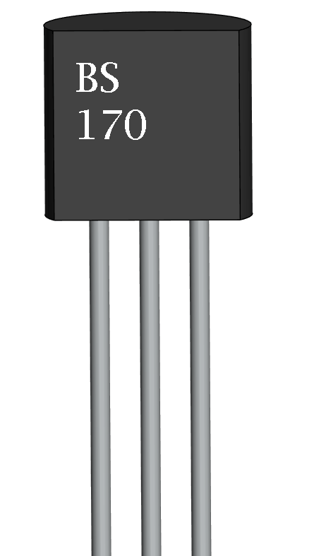
Pin Configuration and Descriptions
The N-MOSFET typically has three pins: Gate (G), Drain (D), and Source (S). Some models may include a fourth pin for the substrate or body (commonly tied to the source). Below is the pin configuration:
| Pin | Name | Description |
|---|---|---|
| 1 | Gate (G) | Controls the flow of current between the drain and source. A positive voltage |
| applied here turns the MOSFET on. | ||
| 2 | Drain (D) | The terminal through which current flows when the MOSFET is on. |
| 3 | Source (S) | The terminal through which current exits the MOSFET. |
Usage Instructions
How to Use the N-MOSFET in a Circuit
- Determine the Operating Voltage and Current: Ensure the N-MOSFET's voltage and current ratings meet the requirements of your circuit.
- Connect the Terminals:
- Connect the source to the ground or the negative terminal of the power supply.
- Connect the drain to the load (e.g., a motor or LED) and then to the positive terminal of the power supply.
- Apply a control signal to the gate to turn the MOSFET on or off.
- Gate Resistor: Use a resistor (typically 10Ω to 1kΩ) between the gate and the control signal to limit inrush current and protect the gate.
- Flyback Diode: For inductive loads (e.g., motors), add a flyback diode across the load to protect the MOSFET from voltage spikes.
Important Considerations and Best Practices
- Gate Drive Voltage: Ensure the gate voltage is sufficient to fully turn on the MOSFET (check the VGS(th) threshold in the datasheet).
- Heat Dissipation: Use a heatsink or proper cooling if the MOSFET dissipates significant power.
- Avoid Overvoltage: Do not exceed the maximum VDS or VGS ratings to prevent damage.
- Switching Speed: Use a gate driver circuit for high-speed switching applications to minimize switching losses.
Example: Controlling an LED with an Arduino UNO
Below is an example of using an N-MOSFET to control an LED with an Arduino UNO.
Circuit Diagram
- Source: Connected to ground.
- Drain: Connected to the negative terminal of the LED (positive terminal of the LED connected to a resistor and then to +5V).
- Gate: Connected to an Arduino digital pin (e.g., pin 9) through a 220Ω resistor.
Arduino Code
// Define the pin connected to the MOSFET gate
const int mosfetGatePin = 9;

void setup() {
  pinMode(mosfetGatePin, OUTPUT); // Set the MOSFET gate pin as an output
}

void loop() {
  digitalWrite(mosfetGatePin, HIGH); // Turn the MOSFET on (LED lights up)
  delay(1000); // Wait for 1 second
  digitalWrite(mosfetGatePin, LOW);  // Turn the MOSFET off (LED turns off)
  delay(1000); // Wait for 1 second
}
Troubleshooting and FAQs
Common Issues and Solutions
MOSFET Not Turning On:
- Cause: Insufficient gate voltage.
- Solution: Check the VGS(th) value in the datasheet and ensure the gate voltage exceeds this threshold.
Excessive Heat:
- Cause: High current or poor heat dissipation.
- Solution: Use a heatsink or a MOSFET with a lower RDS(on) value.
MOSFET Always On or Off:
- Cause: Gate signal not properly connected or damaged MOSFET.
- Solution: Verify the gate signal and replace the MOSFET if necessary.
Voltage Spikes Damaging the MOSFET:
- Cause: Inductive load without a flyback diode.
- Solution: Add a flyback diode across the load.
FAQs
Q: Can I use an N-MOSFET for high-side switching?
A: While N-MOSFETs are typically used for low-side switching, they can be used for high-side switching with a proper gate driver circuit to provide the required gate voltage.
Q: How do I choose the right N-MOSFET for my application?
A: Consider the voltage, current, RDS(on), and power dissipation ratings. Ensure they meet or exceed the requirements of your circuit.
Q: Do I need a gate resistor?
A: Yes, a gate resistor (e.g., 220Ω) helps limit inrush current and protects the gate from damage.
Q: Can I drive an N-MOSFET directly with an Arduino?
A: Yes, if the MOSFET is a logic-level type with a low VGS(th). Otherwise, use a gate driver circuit.