Cirkit Designer Logo
Cirkit Designer
Your all-in-one circuit design IDE
Home / 
Component Documentation

How to Use esp32 s3: Examples, Pinouts, and Specs

Image of esp32 s3
Cirkit Designer LogoDesign with esp32 s3 in Cirkit Designer

Introduction

The ESP32-S3, manufactured by Espressif Systems, is a high-performance microcontroller designed for Internet of Things (IoT) applications. It features integrated Wi-Fi and Bluetooth Low Energy (BLE) capabilities, a dual-core processor, and enhanced AI acceleration. With its rich set of peripherals and support for real-time processing, the ESP32-S3 is ideal for applications such as smart home devices, wearables, industrial automation, and edge AI solutions.

Explore Projects Built with esp32 s3

Use Cirkit Designer to design, explore, and prototype these projects online. Some projects support real-time simulation. Click "Open Project" to start designing instantly!
ESP32-S3 Based Automated Watering System with Ultrasonic Sensing and Data Logging
Image of galon otomatis telegram: A project utilizing esp32 s3 in a practical application
This circuit features an ESP32-S3 microcontroller connected to various peripherals including an HC-SR04 ultrasonic sensor, a water flow sensor, an OLED display, a DS3231 real-time clock (RTC), an SD card module, a water pump, a two-channel relay, and a valve solenoid. The ESP32-S3 manages sensor readings, data logging, and controls the water pump and valve via the relay based on sensor inputs. The circuit is designed for monitoring and controlling water flow, likely in an automated irrigation or fluid management system.
Cirkit Designer LogoOpen Project in Cirkit Designer
ESP32-S3 Based Environmental Monitoring and Control System with Data Logging
Image of ESP32: A project utilizing esp32 s3 in a practical application
This circuit features an ESP32-S3 microcontroller interfaced with various sensors and modules, including a DHT22 temperature and humidity sensor, an HC-SR04 ultrasonic sensor, an SGP41 VOC and NOx sensor, and an Adafruit INA260 current and power sensor. The ESP32-S3 also controls a DC motor via a relay and communicates with an SD card and an OLED display. An Arduino UNO is used to read inputs from a rotary encoder, and a step-down buck converter is used to regulate voltage from a 12V battery to power the components.
Cirkit Designer LogoOpen Project in Cirkit Designer
ESP32-S3 Based Vibration Detection System with TFT Display and Power Backup
Image of IOT Thesis: A project utilizing esp32 s3 in a practical application
This circuit features an ESP32-S3 microcontroller connected to various peripherals including an ADXL355 accelerometer, an SW-420 vibration sensor, a buzzer module, and an ILI9341 TFT display. The ESP32-S3 manages sensor inputs and provides output to the display and buzzer. Power management is handled by a 12V to 5V step-down converter, and a UPS ensures uninterrupted power supply, with a rocker switch to control the power flow.
Cirkit Designer LogoOpen Project in Cirkit Designer
ESP32-S3 GPS and Wind Speed Logger with Dual OLED Displays and CAN Bus
Image of esp32-s3-ellipse: A project utilizing esp32 s3 in a practical application
This circuit features an ESP32-S3 microcontroller interfaced with an SD card module, two OLED displays, a GPS module, and a CAN bus module. The ESP32-S3 records GPS data to the SD card, displays speed on one OLED, and shows wind speed from the CAN bus on the other OLED, providing a comprehensive data logging and display system.
Cirkit Designer LogoOpen Project in Cirkit Designer

Explore Projects Built with esp32 s3

Use Cirkit Designer to design, explore, and prototype these projects online. Some projects support real-time simulation. Click "Open Project" to start designing instantly!
Image of galon otomatis telegram: A project utilizing esp32 s3 in a practical application
ESP32-S3 Based Automated Watering System with Ultrasonic Sensing and Data Logging
This circuit features an ESP32-S3 microcontroller connected to various peripherals including an HC-SR04 ultrasonic sensor, a water flow sensor, an OLED display, a DS3231 real-time clock (RTC), an SD card module, a water pump, a two-channel relay, and a valve solenoid. The ESP32-S3 manages sensor readings, data logging, and controls the water pump and valve via the relay based on sensor inputs. The circuit is designed for monitoring and controlling water flow, likely in an automated irrigation or fluid management system.
Cirkit Designer LogoOpen Project in Cirkit Designer
Image of ESP32: A project utilizing esp32 s3 in a practical application
ESP32-S3 Based Environmental Monitoring and Control System with Data Logging
This circuit features an ESP32-S3 microcontroller interfaced with various sensors and modules, including a DHT22 temperature and humidity sensor, an HC-SR04 ultrasonic sensor, an SGP41 VOC and NOx sensor, and an Adafruit INA260 current and power sensor. The ESP32-S3 also controls a DC motor via a relay and communicates with an SD card and an OLED display. An Arduino UNO is used to read inputs from a rotary encoder, and a step-down buck converter is used to regulate voltage from a 12V battery to power the components.
Cirkit Designer LogoOpen Project in Cirkit Designer
Image of IOT Thesis: A project utilizing esp32 s3 in a practical application
ESP32-S3 Based Vibration Detection System with TFT Display and Power Backup
This circuit features an ESP32-S3 microcontroller connected to various peripherals including an ADXL355 accelerometer, an SW-420 vibration sensor, a buzzer module, and an ILI9341 TFT display. The ESP32-S3 manages sensor inputs and provides output to the display and buzzer. Power management is handled by a 12V to 5V step-down converter, and a UPS ensures uninterrupted power supply, with a rocker switch to control the power flow.
Cirkit Designer LogoOpen Project in Cirkit Designer
Image of esp32-s3-ellipse: A project utilizing esp32 s3 in a practical application
ESP32-S3 GPS and Wind Speed Logger with Dual OLED Displays and CAN Bus
This circuit features an ESP32-S3 microcontroller interfaced with an SD card module, two OLED displays, a GPS module, and a CAN bus module. The ESP32-S3 records GPS data to the SD card, displays speed on one OLED, and shows wind speed from the CAN bus on the other OLED, providing a comprehensive data logging and display system.
Cirkit Designer LogoOpen Project in Cirkit Designer

Common Applications

  • Smart home automation systems
  • Wearable devices
  • Industrial IoT and automation
  • AI-powered edge computing
  • Wireless sensor networks
  • Robotics and drones

Technical Specifications

Key Features

  • Processor: Dual-core Xtensa LX7, up to 240 MHz
  • Memory: 512 KB SRAM, support for external PSRAM
  • Wireless Connectivity:
    • Wi-Fi: 802.11 b/g/n (2.4 GHz)
    • Bluetooth: BLE 5.0 + Bluetooth Mesh
  • AI Acceleration: Vector instructions for AI/ML workloads
  • GPIO Pins: Up to 45 configurable GPIOs
  • Peripherals:
    • SPI, I2C, I2S, UART, PWM, ADC, DAC
    • USB OTG support
  • Operating Voltage: 3.0V to 3.6V
  • Power Consumption: Ultra-low power modes for battery-powered applications
  • Package: QFN48 or QFN68

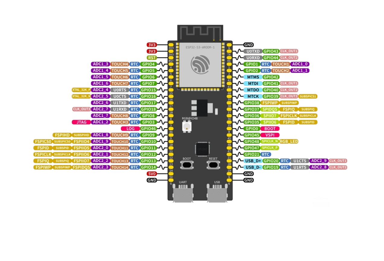
Pin Configuration and Descriptions

The ESP32-S3 has a flexible pinout, with up to 45 GPIOs that can be configured for various functions. Below is a table of commonly used pins and their default functions:

Pin Name Default Function Description
GPIO0 Boot Mode Selection Used to enter bootloader mode during flashing.
GPIO1 UART TX Default UART transmit pin.
GPIO3 UART RX Default UART receive pin.
GPIO18 SPI CLK Clock signal for SPI communication.
GPIO19 SPI MISO Master In Slave Out for SPI.
GPIO23 SPI MOSI Master Out Slave In for SPI.
GPIO25 DAC1 Digital-to-Analog Converter channel 1.
GPIO26 DAC2 Digital-to-Analog Converter channel 2.
GPIO32 ADC1_CH4 Analog-to-Digital Converter channel 4.
GPIO33 ADC1_CH5 Analog-to-Digital Converter channel 5.
GPIO36 ADC1_CH0 Analog-to-Digital Converter channel 0.
GPIO39 ADC1_CH3 Analog-to-Digital Converter channel 3.
EN Chip Enable Enables or disables the chip.
3V3 Power Supply 3.3V power input.
GND Ground Ground connection.

Note: Many GPIOs are multiplexed and can be configured for alternate functions using the ESP-IDF or Arduino IDE.

Usage Instructions

Using the ESP32-S3 in a Circuit

  1. Power Supply: Ensure the ESP32-S3 is powered with a stable 3.3V supply. Avoid exceeding 3.6V to prevent damage.
  2. Boot Mode: To flash firmware, connect GPIO0 to GND and reset the chip. After flashing, disconnect GPIO0 from GND.
  3. Peripherals: Connect peripherals (e.g., sensors, actuators) to the appropriate GPIO pins. Use pull-up or pull-down resistors as needed.
  4. Programming: The ESP32-S3 can be programmed using the Arduino IDE, ESP-IDF, or other compatible environments.

Example: Blinking an LED with Arduino IDE

Below is an example of how to blink an LED connected to GPIO2 using the Arduino IDE:

// Define the GPIO pin where the LED is connected
#define LED_PIN 2

void setup() {
  // Set the LED pin as an output
  pinMode(LED_PIN, OUTPUT);
}

void loop() {
  // Turn the LED on
  digitalWrite(LED_PIN, HIGH);
  delay(1000); // Wait for 1 second

  // Turn the LED off
  digitalWrite(LED_PIN, LOW);
  delay(1000); // Wait for 1 second
}

Important Considerations

  • Voltage Levels: Ensure all connected devices operate at 3.3V logic levels. Use level shifters if interfacing with 5V devices.
  • Heat Management: For high-performance applications, consider adding a heatsink or ensuring proper ventilation.
  • Firmware Updates: Regularly update the firmware to benefit from the latest features and security patches.

Troubleshooting and FAQs

Common Issues

  1. Device Not Detected During Flashing:

    • Ensure GPIO0 is connected to GND during the flashing process.
    • Verify that the USB cable is functional and supports data transfer.
    • Check the drivers for the USB-to-serial converter (e.g., CP210x or CH340).
  2. Wi-Fi Connection Fails:

    • Verify the SSID and password in your code.
    • Ensure the router operates on the 2.4 GHz band (ESP32-S3 does not support 5 GHz Wi-Fi).
  3. Random Resets or Instability:

    • Check the power supply for stability and sufficient current (at least 500 mA).
    • Avoid using GPIOs that are reserved for internal functions.
  4. GPIO Pin Not Working:

    • Confirm the pin is not being used for another function (e.g., ADC, DAC).
    • Check for proper pull-up or pull-down resistors if required.

FAQs

Q: Can the ESP32-S3 run AI models?
A: Yes, the ESP32-S3 includes vector instructions optimized for AI/ML workloads, making it suitable for lightweight AI models.

Q: How do I reduce power consumption?
A: Use the ultra-low power (ULP) co-processor and deep sleep modes. Disable unused peripherals to save power.

Q: Can I use the ESP32-S3 with Arduino libraries?
A: Yes, the ESP32-S3 is fully supported in the Arduino IDE, and most ESP32 libraries are compatible.

Q: What is the maximum range of Wi-Fi and Bluetooth?
A: Wi-Fi range is typically up to 50 meters indoors and 200 meters outdoors. Bluetooth range depends on the environment but is generally around 10-15 meters.

By following this documentation, users can effectively integrate the ESP32-S3 into their projects and troubleshoot common issues.