How to Use BNO-055: Examples, Pinouts, and Specs
Introduction
The BNO-055 is a 9-axis absolute orientation sensor that integrates a 3-axis accelerometer, a 3-axis gyroscope, and a 3-axis magnetometer. Unlike traditional sensors that require external processing, the BNO-055 features an onboard microcontroller that fuses sensor data to provide accurate orientation information in real-time. This makes it an excellent choice for applications requiring precise motion tracking, such as robotics, drones, augmented reality, and wearable devices.
Explore Projects Built with BNO-055
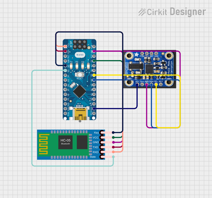

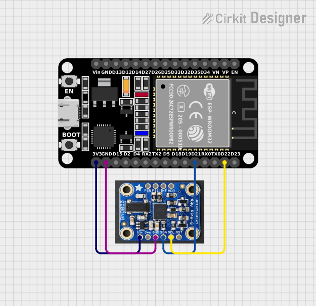
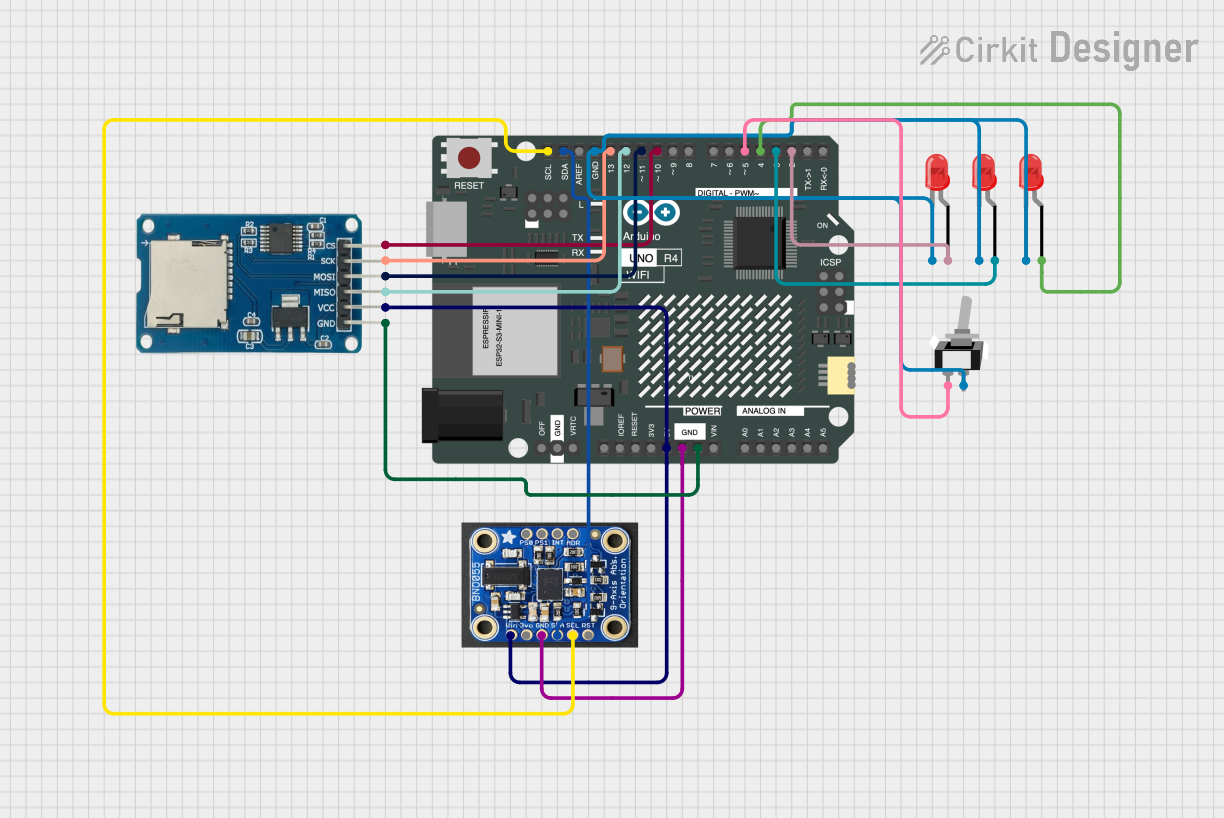
Explore Projects Built with BNO-055
Common Applications:
- Robotics for navigation and stabilization
- Drones for flight control and orientation
- Motion tracking in virtual reality (VR) and augmented reality (AR)
- Wearable devices for fitness and health monitoring
- Industrial automation and control systems
Technical Specifications
The BNO-055 is a highly versatile sensor with the following key specifications:
| Parameter | Value |
|---|---|
| Operating Voltage | 2.4V to 3.6V |
| Communication Interfaces | I²C, UART, SPI |
| Power Consumption | 12 mA (typical in normal mode) |
| Operating Temperature | -40°C to +85°C |
| Accelerometer Range | ±2g, ±4g, ±8g, ±16g |
| Gyroscope Range | ±125°/s, ±250°/s, ±500°/s, ±1000°/s, ±2000°/s |
| Magnetometer Range | ±1300 µT |
| Output Data Rate | Up to 100 Hz |
| Dimensions | 3.8 mm x 5.2 mm x 1.1 mm |
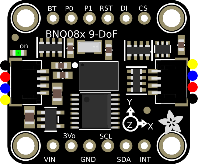
Pin Configuration
The BNO-055 has 10 pins, as described in the table below:
| Pin | Name | Description |
|---|---|---|
| 1 | GND | Ground connection |
| 2 | VDD | Power supply (2.4V to 3.6V) |
| 3 | SDA | I²C data line (or UART TX in UART mode) |
| 4 | SCL | I²C clock line (or UART RX in UART mode) |
| 5 | PS0 | Protocol selection pin 0 (used to select I²C, UART, or SPI mode) |
| 6 | PS1 | Protocol selection pin 1 (used to select I²C, UART, or SPI mode) |
| 7 | RST | Reset pin (active low) |
| 8 | INT | Interrupt pin (used for event notifications) |
| 9 | BOOT | Boot mode selection pin |
| 10 | NC | Not connected |
Usage Instructions
Connecting the BNO-055 to an Arduino UNO
The BNO-055 can be easily interfaced with an Arduino UNO using the I²C protocol. Below is a step-by-step guide:
Wiring:
- Connect the
VDDpin of the BNO-055 to the 3.3V pin on the Arduino. - Connect the
GNDpin of the BNO-055 to the GND pin on the Arduino. - Connect the
SDApin of the BNO-055 to the A4 pin on the Arduino (I²C data line). - Connect the
SCLpin of the BNO-055 to the A5 pin on the Arduino (I²C clock line). - Set the
PS0andPS1pins toLOWto enable I²C mode.
- Connect the
Install Required Libraries:
- Install the "Adafruit BNO055" library from the Arduino Library Manager.
Example Code: Use the following code to read orientation data from the BNO-055:
#include <Wire.h>
#include <Adafruit_Sensor.h>
#include <Adafruit_BNO055.h>

// Create an instance of the BNO055 sensor
Adafruit_BNO055 bno = Adafruit_BNO055(55);

void setup() {
  Serial.begin(9600);
  // Initialize the BNO055 sensor
  if (!bno.begin()) {
    Serial.println("BNO055 not detected. Check wiring or I2C address!");
    while (1);
  }
  Serial.println("BNO055 initialized successfully!");
  bno.setExtCrystalUse(true); // Use external crystal for better accuracy
}

void loop() {
  // Get orientation data (Euler angles)
  sensors_event_t event;
  bno.getEvent(&event);

  // Print orientation data to the Serial Monitor
  Serial.print("Heading: ");
  Serial.print(event.orientation.x);
  Serial.print("°, Pitch: ");
  Serial.print(event.orientation.y);
  Serial.print("°, Roll: ");
  Serial.print(event.orientation.z);
  Serial.println("°");

  delay(100); // Delay for readability
}
Important Considerations:
- Power Supply: Ensure the BNO-055 is powered with 3.3V. Using 5V may damage the sensor.
- Pull-Up Resistors: If your I²C bus does not have pull-up resistors, add 4.7kΩ resistors between
SDA/SCLandVDD. - External Crystal: Enabling the external crystal improves accuracy and stability.
- Mounting Orientation: Ensure the sensor is mounted correctly to avoid incorrect orientation readings.
Troubleshooting and FAQs
Common Issues and Solutions:
BNO-055 Not Detected:
- Cause: Incorrect wiring or I²C address mismatch.
- Solution: Double-check the connections and ensure the
PS0andPS1pins are set for I²C mode. Verify the I²C address in the code (default is0x28).
Inaccurate Orientation Data:
- Cause: Sensor not calibrated.
- Solution: Perform a full calibration by moving the sensor in all axes. Use the Adafruit library's calibration example for guidance.
No Data Output:
- Cause: Incorrect baud rate or sensor initialization failure.
- Solution: Ensure the baud rate in the code matches the Serial Monitor. Check for initialization errors in the setup.
Random Spikes in Data:
- Cause: Electrical noise or unstable power supply.
- Solution: Use decoupling capacitors near the sensor and ensure a stable 3.3V power source.
FAQs:
Q: Can the BNO-055 be used with a 5V microcontroller?
- A: Yes, but you must use a logic level shifter for the I²C lines and power the sensor with 3.3V.
Q: How do I reset the BNO-055?
- A: Pull the
RSTpin low for at least 1 ms, then release it.
- A: Pull the
Q: What is the maximum cable length for I²C communication?
- A: The maximum length depends on the pull-up resistor values and the I²C clock speed. For standard setups, keep the cable length under 1 meter.
Q: Can I use the BNO-055 in SPI mode?
- A: Yes, the BNO-055 supports SPI communication. Refer to the datasheet for SPI-specific wiring and configuration.
By following this documentation, you can effectively integrate the BNO-055 into your projects and troubleshoot common issues.