How to Use ADM1087: Examples, Pinouts, and Specs
Introduction
The ADM1087 is a versatile and precise voltage monitoring and supervision circuit designed for a variety of applications, including power supply monitoring, system reset generation, and voltage sequencing. This component is essential for ensuring the reliability and stability of electronic systems by providing accurate voltage supervision.
Explore Projects Built with ADM1087
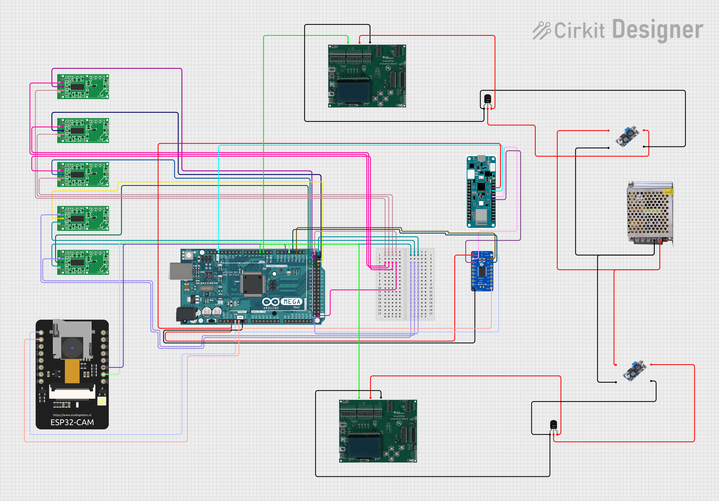

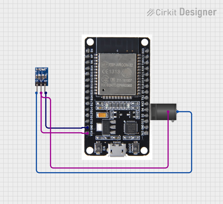

Explore Projects Built with ADM1087
Common Applications and Use Cases
- Power Supply Monitoring: Ensures that the power supply is within specified limits.
- System Reset Generation: Generates a reset signal when the monitored voltage falls out of the predefined range, which can be used to reset microcontrollers and other digital systems.
- Voltage Sequencing: Controls the power-up and power-down sequence of multiple voltages in a system.
Technical Specifications
Key Technical Details
- Supply Voltage Range: 2.5 V to 5.5 V
- Operating Temperature Range: -40°C to +125°C
- Reset Threshold Voltage Options: Factory-programmed options from 1.58 V to 4.63 V
- Reset Output Stage: Push-pull, active low
- Reset Timeout Period: Adjustable with external capacitor
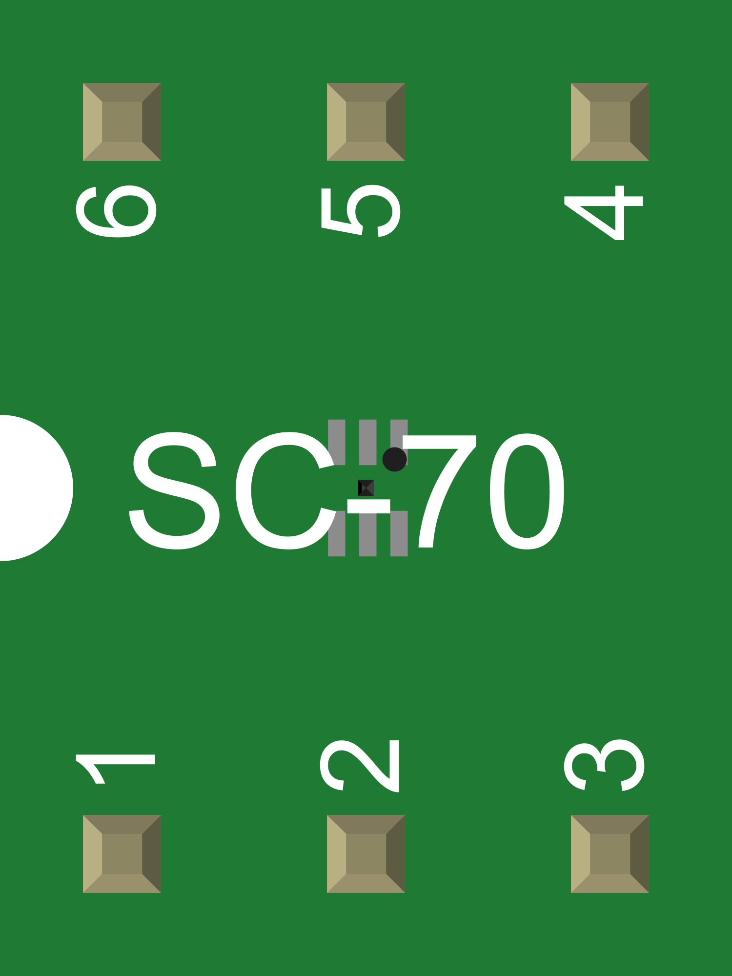
Pin Configuration and Descriptions
| Pin Number | Name | Description |
|---|---|---|
| 1 | GND | Ground reference for the circuit. |
| 2 | RESET | Active low reset output. |
| 3 | MR | Manual reset input, active low. |
| 4 | VCC | Supply voltage input. |
| 5 | CT | Connect to an external capacitor to set the reset timeout period. |
| 6 | SENSE | Voltage sense input. Monitors the voltage to be supervised. |
Usage Instructions
How to Use the ADM1087 in a Circuit
- Power Supply Connection: Connect the VCC pin to the supply voltage within the specified range (2.5 V to 5.5 V).
- Ground Connection: Connect the GND pin to the system ground.
- Voltage Monitoring: Connect the SENSE pin to the voltage node that needs to be monitored.
- Reset Output: Connect the RESET pin to the reset input of the device that requires supervision.
- Manual Reset (Optional): If manual reset functionality is desired, connect a normally open push-button switch between the MR pin and ground. Otherwise, tie the MR pin to VCC if not used.
- Reset Timeout Period: Connect a capacitor to the CT pin to set the desired reset timeout period. The timeout period is the minimum duration the RESET signal will be held active after a fault condition is corrected.
Important Considerations and Best Practices
- Ensure that the voltage at the SENSE pin does not exceed the VCC supply voltage.
- The RESET output can directly interface with most microcontroller reset inputs.
- The external capacitor connected to the CT pin should have a low leakage current to maintain accuracy of the timeout period.
- Avoid long traces to the SENSE pin to minimize noise pickup.
- Decouple the VCC pin with a 0.1 µF ceramic capacitor close to the ADM1087 to filter out supply noise.
Troubleshooting and FAQs
Common Issues
- No Reset Signal: Check the voltage at the SENSE pin to ensure it is below the threshold. Also, verify that the MR pin is not being inadvertently pulled low.
- Reset Signal Always Active: Ensure that the voltage at the SENSE pin is above the threshold and that the capacitor at the CT pin is correctly sized for the desired timeout period.
Solutions and Tips for Troubleshooting
- If the RESET signal is not behaving as expected, double-check the connections to the SENSE, MR, and CT pins.
- Verify that the supply voltage is within the specified range and is stable.
- Inspect the external capacitor at the CT pin for proper value and integrity.
FAQs
Q: Can the ADM1087 be used with voltages higher than 5.5 V? A: No, the ADM1087 is designed to operate within a supply voltage range of 2.5 V to 5.5 V. Using higher voltages can damage the device.
Q: How do I choose the reset threshold voltage? A: The reset threshold voltage is factory-programmed and should be chosen based on the voltage level you wish to monitor. Select a threshold that is safely below the normal operating voltage to allow for tolerances and transients.
Q: What is the purpose of the manual reset input (MR)? A: The MR pin allows for a manual reset of the system by pulling the pin low, which can be useful for testing and debugging purposes.
Example Code for Arduino UNO
// Example code to demonstrate how to interface the ADM1087 with an Arduino UNO
// The ADM1087 RESET pin is connected to the Arduino's digital pin 2

const int resetPin = 2; // RESET pin connected to digital pin 2

void setup() {
  pinMode(resetPin, INPUT); // Set the RESET pin as an input
  Serial.begin(9600); // Initialize serial communication at 9600 bps
}

void loop() {
  // Check the state of the RESET pin
  if (digitalRead(resetPin) == LOW) {
    // If the RESET pin is LOW, a reset condition is present
    Serial.println("Reset condition detected!");
    // Implement any desired response to a reset condition here
  } else {
    // If the RESET pin is HIGH, the voltage is within the acceptable range
    Serial.println("Voltage is within the acceptable range.");
  }
  delay(1000); // Wait for 1 second before checking again
}
Remember to keep the code comments concise and within the 80 character line length limit. This example demonstrates a simple way to monitor the reset condition using an Arduino UNO.