How to Use AD620an ic: Examples, Pinouts, and Specs
Introduction
The AD620AN is an instrumentation amplifier IC designed for high accuracy and low power consumption. It is manufactured by Analog Devices and is widely used in applications that require precise amplification of small differential signals. Common use cases include medical instrumentation, data acquisition systems, and industrial process controls.
Explore Projects Built with AD620an ic

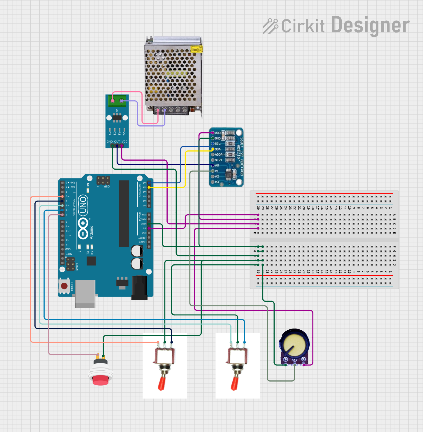
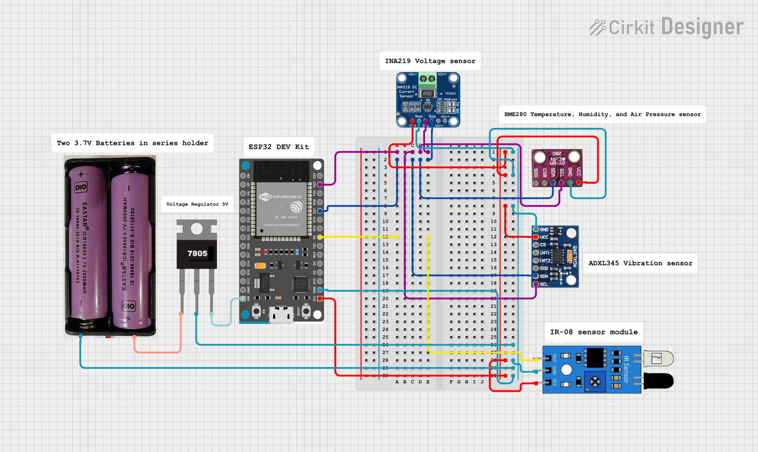
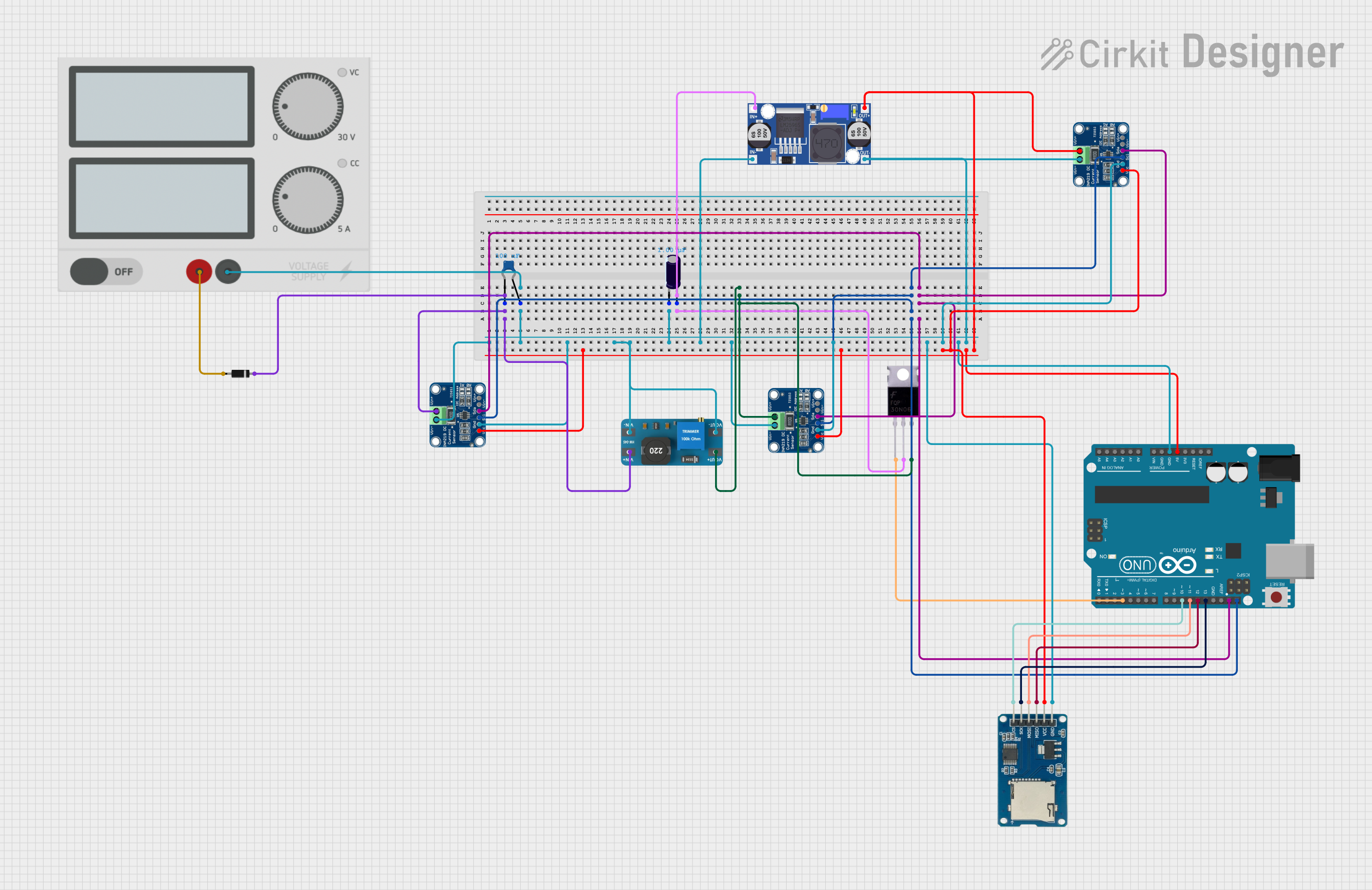
Explore Projects Built with AD620an ic
Technical Specifications
Key Technical Details
| Parameter | Value |
|---|---|
| Supply Voltage | ±2.3V to ±18V |
| Input Voltage Range | ±2V to ±10V |
| Gain Range | 1 to 1000 (set by external resistor) |
| Input Bias Current | 1.0 nA (typical) |
| Input Offset Voltage | 50 µV (typical) |
| Common-Mode Rejection | 100 dB (minimum) |
| Power Consumption | 1.3 mA (typical) |
| Operating Temperature | -40°C to +85°C |
| Package | 8-Pin Plastic DIP |
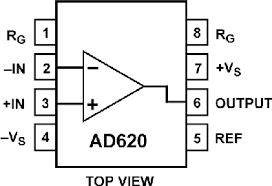
Pin Configuration and Descriptions
| Pin Number | Pin Name | Description |
|---|---|---|
| 1 | RG | Gain Setting Resistor (connect to external resistor) |
| 2 | -IN | Inverting Input |
| 3 | +IN | Non-Inverting Input |
| 4 | -VS | Negative Power Supply |
| 5 | Ref | Reference Voltage Input |
| 6 | Output | Output Voltage |
| 7 | +VS | Positive Power Supply |
| 8 | RG | Gain Setting Resistor (connect to external resistor) |
Usage Instructions
How to Use the AD620AN in a Circuit
Power Supply: Connect the positive power supply to pin 7 (+VS) and the negative power supply to pin 4 (-VS). Ensure the supply voltage is within the specified range (±2.3V to ±18V).
Input Connections: Connect the differential signal to be amplified to pins 2 (-IN) and 3 (+IN).
Gain Setting: The gain of the AD620AN is set by an external resistor connected between pins 1 and 8 (RG). The gain (G) can be calculated using the formula: [ G = 1 + \frac{49.4k\Omega}{R_G} ] where ( R_G ) is the value of the external resistor in ohms.
Reference Voltage: Connect the reference voltage to pin 5 (Ref). This pin is typically connected to ground if no offset is required.
Output: The amplified output signal is available at pin 6 (Output).
Important Considerations and Best Practices
- Power Supply Decoupling: Use decoupling capacitors (e.g., 0.1 µF ceramic and 10 µF electrolytic) close to the power supply pins to reduce noise and improve stability.
- Input Protection: Use series resistors and clamping diodes to protect the inputs from voltage spikes and overvoltage conditions.
- PCB Layout: Ensure a clean and low-noise PCB layout by keeping the input traces short and away from noisy signals. Use a ground plane to minimize interference.
Troubleshooting and FAQs
Common Issues and Solutions
No Output Signal:
- Check Power Supply: Ensure the power supply is connected and within the specified voltage range.
- Verify Connections: Check all connections, especially the input and gain setting resistor.
Output Signal is Distorted:
- Input Signal Range: Ensure the input signal is within the specified input voltage range.
- Power Supply Decoupling: Add or check decoupling capacitors to reduce noise.
Incorrect Gain:
- Gain Resistor: Verify the value of the external gain resistor (RG) and recalculate the gain using the formula provided.
FAQs
Q: Can the AD620AN be used with a single power supply? A: Yes, the AD620AN can be used with a single power supply. Connect the negative power supply pin (-VS) to ground and the positive power supply pin (+VS) to the positive voltage.
Q: How do I minimize the offset voltage? A: To minimize offset voltage, ensure proper PCB layout, use low-offset components, and consider temperature compensation techniques.
Q: Can I use the AD620AN for AC signals? A: Yes, the AD620AN can amplify AC signals. Ensure proper coupling capacitors are used to block any DC components if necessary.
Example Code for Arduino UNO
Below is an example code to interface the AD620AN with an Arduino UNO to read an amplified sensor signal:
// Define the analog input pin
const int analogPin = A0;

void setup() {
  // Initialize serial communication at 9600 baud rate
  Serial.begin(9600);
}

void loop() {
  // Read the analog value from the AD620AN output
  int sensorValue = analogRead(analogPin);

  // Convert the analog value to voltage (assuming 5V reference)
  float voltage = sensorValue * (5.0 / 1023.0);

  // Print the voltage to the serial monitor
  Serial.print("Voltage: ");
  Serial.println(voltage);

  // Wait for 500 milliseconds before the next reading
  delay(500);
}
This code reads the amplified signal from the AD620AN output connected to the Arduino analog pin A0 and prints the corresponding voltage to the serial monitor.
This documentation provides a comprehensive guide to understanding, using, and troubleshooting the AD620AN instrumentation amplifier IC. Whether you are a beginner or an experienced user, this guide aims to help you effectively utilize this component in your projects.