Cirkit Designer Logo
Cirkit Designer
Your all-in-one circuit design IDE
Home / 
Component Documentation

How to Use Adafruit PyRuler: Examples, Pinouts, and Specs

Image of Adafruit PyRuler
Cirkit Designer LogoDesign with Adafruit PyRuler in Cirkit Designer

Introduction

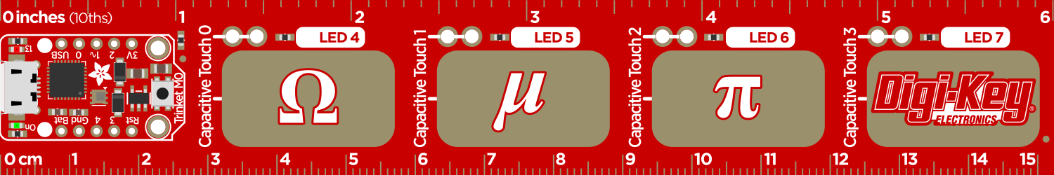
The Adafruit PyRuler is an innovative measuring tool tailored for electronics hobbyists, engineers, and makers. It is not only a physical ruler with measurement units in millimeters and inches but also integrates electronic components that allow it to function as a touch-sensitive input device when connected to a computer or microcontroller. The PyRuler features capacitive touch pads that can be programmed to perform various functions, making it a versatile tool for both measurement tasks and interactive projects.

Explore Projects Built with Adafruit PyRuler

Use Cirkit Designer to design, explore, and prototype these projects online. Some projects support real-time simulation. Click "Open Project" to start designing instantly!
Adafruit MPU6050 and VL6180X Sensor Interface with Servo Control
Image of wire: A project utilizing Adafruit PyRuler in a practical application
This circuit features an Adafruit QT Py microcontroller interfaced with an Adafruit MPU6050 6-axis accelerometer/gyroscope and an Adafruit VL6180X Time of Flight (ToF) distance sensor, both connected via I2C communication. The QT Py also controls a Servomotor SG90, likely for physical actuation based on sensor inputs. The embedded code initializes the sensors, reads their data, and outputs the readings to a serial monitor, with the potential for motion control based on the sensor feedback.
Cirkit Designer LogoOpen Project in Cirkit Designer
Battery-Powered Sensor Hub with Adafruit QT Py RP2040 and OLED Display
Image of 512: A project utilizing Adafruit PyRuler in a practical application
This circuit features an Adafruit QT Py RP2040 microcontroller interfacing with an MPU-6050 accelerometer, an Adafruit APDS-9960 sensor, and a 0.96" OLED display via I2C communication. It is powered by a 3.7V LiPo battery and includes a green LED with a current-limiting resistor connected to an analog pin of the microcontroller.
Cirkit Designer LogoOpen Project in Cirkit Designer
Battery-Powered Smart Sensor Hub with Adafruit QT Py RP2040
Image of wearable final: A project utilizing Adafruit PyRuler in a practical application
This circuit features an Adafruit QT Py RP2040 microcontroller interfaced with an APDS9960 proximity sensor, an MPU6050 accelerometer and gyroscope, and an OLED display via I2C communication. It also includes a buzzer controlled by the microcontroller and is powered by a 3.7V LiPo battery with a toggle switch for power control.
Cirkit Designer LogoOpen Project in Cirkit Designer
Raspberry Pi 3B with I2C Sensor Data Acquisition and OLED Display
Image of Power Meter IoT: A project utilizing Adafruit PyRuler in a practical application
This circuit features a Raspberry Pi 3B as the central processing unit, interfaced with an Adafruit ADS1115 16-bit ADC for analog-to-digital conversion and a 0.96" OLED display for visual output. The ADC is connected to a current sensor for measuring electrical current, and both the ADC and OLED communicate with the Raspberry Pi via the I2C protocol. The circuit is likely used for monitoring current and displaying the measurements in real-time on the OLED screen.
Cirkit Designer LogoOpen Project in Cirkit Designer

Explore Projects Built with Adafruit PyRuler

Use Cirkit Designer to design, explore, and prototype these projects online. Some projects support real-time simulation. Click "Open Project" to start designing instantly!
Image of wire: A project utilizing Adafruit PyRuler in a practical application
Adafruit MPU6050 and VL6180X Sensor Interface with Servo Control
This circuit features an Adafruit QT Py microcontroller interfaced with an Adafruit MPU6050 6-axis accelerometer/gyroscope and an Adafruit VL6180X Time of Flight (ToF) distance sensor, both connected via I2C communication. The QT Py also controls a Servomotor SG90, likely for physical actuation based on sensor inputs. The embedded code initializes the sensors, reads their data, and outputs the readings to a serial monitor, with the potential for motion control based on the sensor feedback.
Cirkit Designer LogoOpen Project in Cirkit Designer
Image of 512: A project utilizing Adafruit PyRuler in a practical application
Battery-Powered Sensor Hub with Adafruit QT Py RP2040 and OLED Display
This circuit features an Adafruit QT Py RP2040 microcontroller interfacing with an MPU-6050 accelerometer, an Adafruit APDS-9960 sensor, and a 0.96" OLED display via I2C communication. It is powered by a 3.7V LiPo battery and includes a green LED with a current-limiting resistor connected to an analog pin of the microcontroller.
Cirkit Designer LogoOpen Project in Cirkit Designer
Image of wearable final: A project utilizing Adafruit PyRuler in a practical application
Battery-Powered Smart Sensor Hub with Adafruit QT Py RP2040
This circuit features an Adafruit QT Py RP2040 microcontroller interfaced with an APDS9960 proximity sensor, an MPU6050 accelerometer and gyroscope, and an OLED display via I2C communication. It also includes a buzzer controlled by the microcontroller and is powered by a 3.7V LiPo battery with a toggle switch for power control.
Cirkit Designer LogoOpen Project in Cirkit Designer
Image of Power Meter IoT: A project utilizing Adafruit PyRuler in a practical application
Raspberry Pi 3B with I2C Sensor Data Acquisition and OLED Display
This circuit features a Raspberry Pi 3B as the central processing unit, interfaced with an Adafruit ADS1115 16-bit ADC for analog-to-digital conversion and a 0.96" OLED display for visual output. The ADC is connected to a current sensor for measuring electrical current, and both the ADC and OLED communicate with the Raspberry Pi via the I2C protocol. The circuit is likely used for monitoring current and displaying the measurements in real-time on the OLED screen.
Cirkit Designer LogoOpen Project in Cirkit Designer

Common Applications and Use Cases

  • PCB design and layout measurement
  • Soldering and component placement assistance
  • Educational tool for teaching electronics and programming
  • Custom input device for computer or microcontroller-based projects

Technical Specifications

Key Technical Details

  • Dimensions: 30.5mm x 155mm x 4mm
  • Weight: 14g
  • Operating Voltage: 3.3V DC
  • Interface: USB or I2C
  • Capacitive Touch Pads: 12 (numbered 0 to 11)
  • Additional Features:
    • Integrated 3V CR1220 coin cell holder for standalone use
    • NeoPixel LED for status indication
    • Onboard STEMMA QT/Qwiic connector for I2C devices

Pin Configuration and Descriptions

Pin Number Description
0-11 Capacitive touch pads
GND Ground
3V 3.3V power supply
SCL I2C clock signal
SDA I2C data signal
RST Reset pin
TX Transmit pin for serial communication
RX Receive pin for serial communication

Usage Instructions

How to Use the PyRuler in a Circuit

  1. Powering the PyRuler:

    • Connect the 3V pin to a 3.3V power source.
    • Ensure the ground pin is connected to the common ground in your circuit.
  2. Connecting to a Computer or Microcontroller:

    • Use a micro USB cable to connect the PyRuler to a computer or compatible microcontroller like an Arduino UNO.
    • The device should be recognized as a USB input device.
  3. Programming the PyRuler:

    • The PyRuler can be programmed using Python, specifically Adafruit's CircuitPython.
    • Write scripts to define the behavior of the capacitive touch pads and NeoPixel LED.

Important Considerations and Best Practices

  • Avoid touching the capacitive pads while powering up the PyRuler to prevent calibration issues.
  • Keep the PyRuler away from conductive materials that might trigger the capacitive touch pads unintentionally.
  • When using the PyRuler as a standalone device, ensure the CR1220 coin cell is properly installed.

Example Code for Arduino UNO

#include <Wire.h>

// Define the I2C address for the PyRuler (if applicable)
#define PYRULER_I2C_ADDRESS 0x00 // Replace with the actual I2C address

void setup() {
  // Initialize serial communication
  Serial.begin(9600);
  // Initialize I2C communication
  Wire.begin();
}

void loop() {
  // Code to interact with the PyRuler's capacitive touch pads
  // and other features would go here.
  // This is a placeholder as the PyRuler is typically programmed with Python.
}

Troubleshooting and FAQs

Common Issues Users Might Face

  • PyRuler Not Recognized by Computer:

    • Ensure the micro USB cable is properly connected and the computer's USB port is functioning.
    • Try using a different USB port or cable.
  • Capacitive Touch Pads Not Responding:

    • Make sure your fingers are not wet or covered with conductive materials.
    • Check that the PyRuler is not resting on a conductive surface.
  • Inaccurate Touch Sensitivity:

    • Recalibrate the touch pads by disconnecting and reconnecting the PyRuler.
    • Avoid holding the PyRuler by the touch pads during power-up.

Solutions and Tips for Troubleshooting

  • If the PyRuler is not functioning as expected, reset the device using the RST pin.
  • Consult the Adafruit PyRuler guide and forums for detailed troubleshooting steps and community support.
  • Ensure that the latest version of CircuitPython is installed on the PyRuler for optimal performance.

FAQs

Q: Can the PyRuler be used with programming languages other than Python? A: While the PyRuler is designed for use with CircuitPython, it may be possible to interact with it using other languages that support USB HID or I2C communication, depending on the specific capabilities and libraries available.

Q: Is the PyRuler compatible with all microcontrollers? A: The PyRuler can be used with microcontrollers that support USB HID or I2C communication. Compatibility may vary, so check the documentation for your specific microcontroller.

Q: How do I update the firmware on the PyRuler? A: Firmware updates for the PyRuler can be done by following the instructions provided by Adafruit for flashing CircuitPython onto the device.