How to Use DM542T stepper driver: Examples, Pinouts, and Specs
Introduction
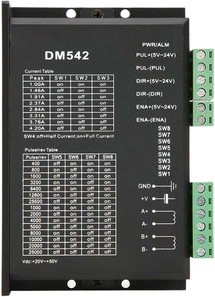
The DM542T stepper motor driver is a high-performance, cost-effective driver designed to precisely control bipolar stepper motors. It is widely used in CNC machines, robotics, and other automation applications where precise motion control is required. The DM542T operates with an advanced DSP algorithm that ensures smooth and accurate motor control.
Explore Projects Built with DM542T stepper driver


Explore Projects Built with DM542T stepper driver
Common Applications and Use Cases
- CNC milling machines and lathes
- 3D printers
- Laser cutters and engravers
- Robotic arms and automation equipment
- Precise positioning systems
Technical Specifications
Key Technical Details
- Input Voltage: 18V to 50V DC
- Output Current: 1.0A to 4.2A (peak) adjustable
- Logic Input Voltage: 5V DC
- Pulse Input Frequency: 0 to 200 kHz
- Microstep Resolutions: Up to 25,600 steps/rev
- Dimensions: 118mm x 75.5mm x 33mm
Pin Configuration and Descriptions
| Pin Number | Signal Name | Description |
|---|---|---|
| 1 | PUL+ | Pulse signal: In single pulse (pulse/direction) mode, this input represents the pulse signal, active on the rising edge. |
| 2 | PUL- | Connected to the negative side of the pulse signal. |
| 3 | DIR+ | Direction signal: This signal determines the direction of motor rotation. |
| 4 | DIR- | Connected to the negative side of the direction signal. |
| 5 | ENA+ | Enable signal: This signal is used to enable or disable the driver. Active low. |
| 6 | ENA- | Connected to the negative side of the enable signal. |
| 7 | A+ | Motor coil A positive connection. |
| 8 | A- | Motor coil A negative connection. |
| 9 | B+ | Motor coil B positive connection. |
| 10 | B- | Motor coil B negative connection. |
| 11 | VCC | Power supply for the internal logic (5V). |
| 12 | GND | Ground for the internal logic. |
Usage Instructions
How to Use the Component in a Circuit
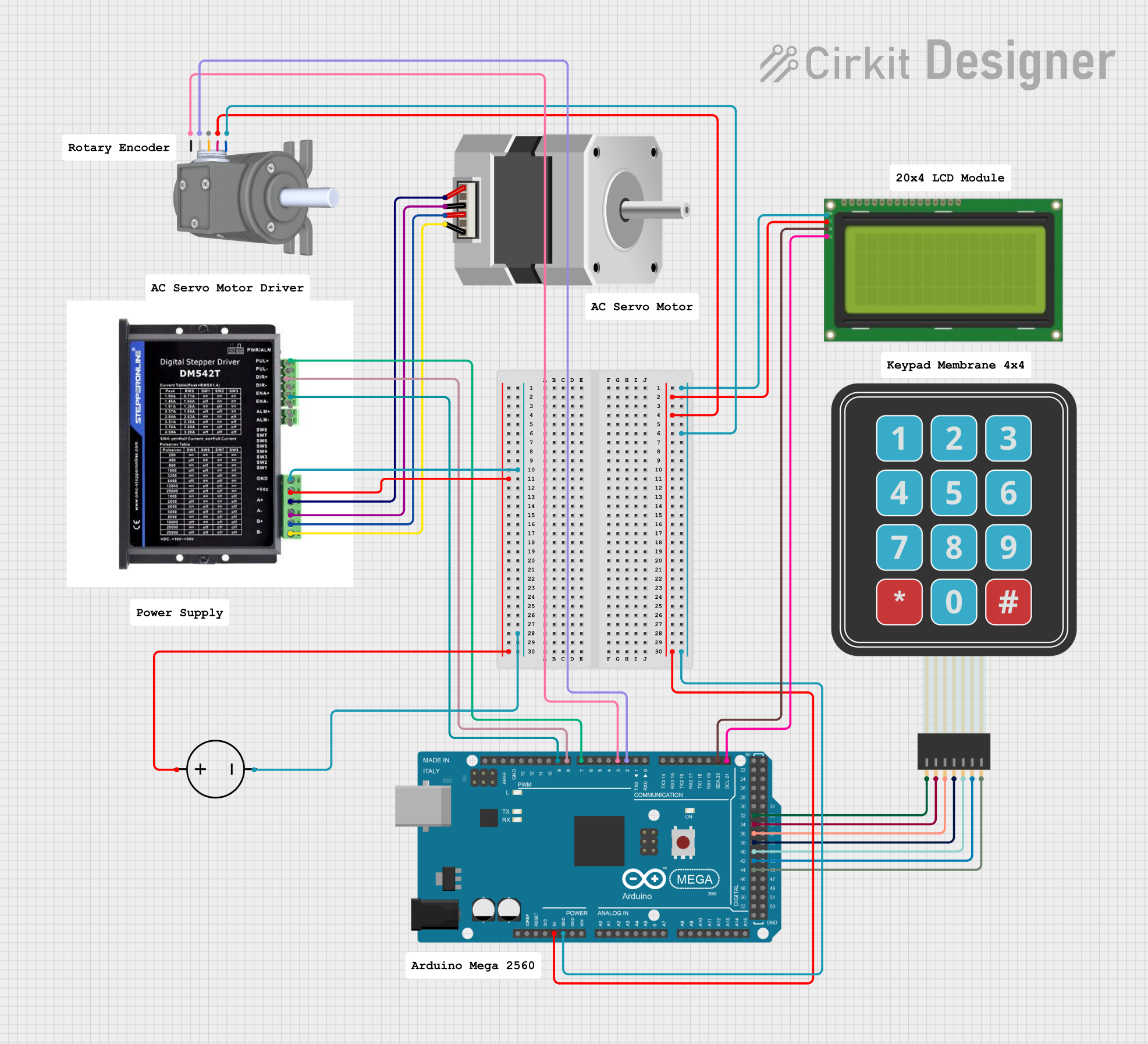
Power Supply Connection: Connect a DC power supply between 18V to 50V to the driver. Ensure the power supply is capable of providing sufficient current for the motor.
Motor Connection: Connect the motor coils to the A+ and A-, B+ and B- terminals on the driver.
Control Signal Connection: Connect the PUL+, PUL-, DIR+, DIR-, ENA+, and ENA- to the respective control signals. Typically, these signals are generated by a microcontroller or motion controller.
Microstep Setting: Set the desired microstep resolution using the DIP switches on the driver.
Current Setting: Adjust the peak current setting according to the motor's specifications using the onboard potentiometer.
Important Considerations and Best Practices
- Always ensure the power supply is turned off before making any connections.
- Use appropriate heat dissipation measures, such as a heatsink, as the driver can generate significant heat during operation.
- Avoid running the motor at its maximum current rating for extended periods to prevent overheating.
- Ensure that the control signals (Pulse, Direction, and Enable) are compatible with the logic level of the driver (5V).
Troubleshooting and FAQs
Common Issues Users Might Face
- Motor not moving: Check power supply, connections, and signal inputs. Ensure the enable signal is active.
- Motor stalling or missing steps: Verify that the current setting is appropriate for the motor. Check for mechanical obstructions or excessive load.
- Driver overheating: Ensure proper heat dissipation and check if the current setting is too high.
Solutions and Tips for Troubleshooting
- Double-check wiring and connections for any loose or incorrect connections.
- Use an oscilloscope to verify the control signals are being received by the driver.
- Reduce the motor's load or increase the current setting slightly, but do not exceed the motor's rated current.
Example Code for Arduino UNO
// Define the stepper motor control pins
#define PUL_PIN 2 // Pulse pin
#define DIR_PIN 3 // Direction pin
#define ENA_PIN 4 // Enable pin

void setup() {
  // Set the control pins as outputs
  pinMode(PUL_PIN, OUTPUT);
  pinMode(DIR_PIN, OUTPUT);
  pinMode(ENA_PIN, OUTPUT);

  // Disable the driver by setting the enable pin high
  digitalWrite(ENA_PIN, HIGH);
}

void loop() {
  // Enable the driver by setting the enable pin low
  digitalWrite(ENA_PIN, LOW);

  // Set the direction of the motor rotation
  digitalWrite(DIR_PIN, HIGH); // Set to LOW for the opposite direction

  // Generate a pulse to move the motor one step
  digitalWrite(PUL_PIN, HIGH);
  delayMicroseconds(500); // Pulse duration (adjust based on motor specs)
  digitalWrite(PUL_PIN, LOW);
  delayMicroseconds(500); // Time between pulses (adjust for speed)

  // Add your code to control the motor based on your application needs
}
Note: The above code is a simple example to demonstrate basic motor movement. For more complex motion control, consider using a stepper motor library like AccelStepper for acceleration and speed control.