
Cirkit Designer
Your all-in-one circuit design IDE
Home /
Component Documentation
How to Use Barrier bar servo motor: Examples, Pinouts, and Specs

 Design with Barrier bar servo motor in Cirkit Designer
Introduction
The Barrier Bar Servo Motor is a specialized servo motor designed to control the movement of barrier bars, commonly used in access control systems. This motor provides precise angular control, making it ideal for applications such as parking lot gates, toll booths, and other vehicle entry/exit management systems. Its robust design ensures reliable operation in both indoor and outdoor environments.
Explore Projects Built with Barrier bar servo motor
Bus Servo Controlled Robotic System with Power Module
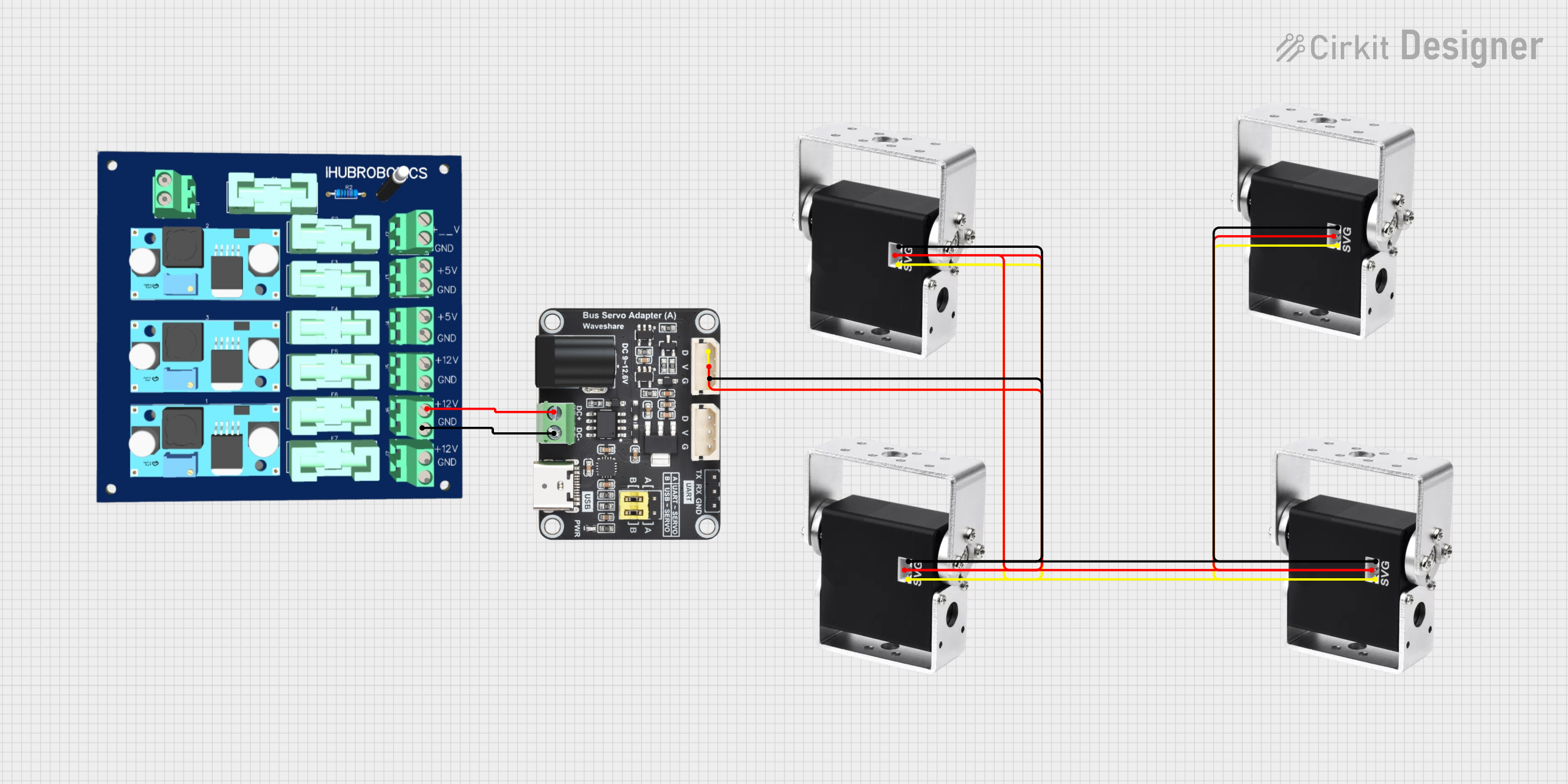
This circuit controls multiple high-torque bus servos using a bus servo adaptor, which is powered by a 6-channel power module. The servos receive their control signals and power through the adaptor, enabling synchronized movement for applications requiring precise and powerful actuation.
Open Project in Cirkit DesignerBattery-Powered ESP32-S3 Controlled Servo System with gForceJoint UART
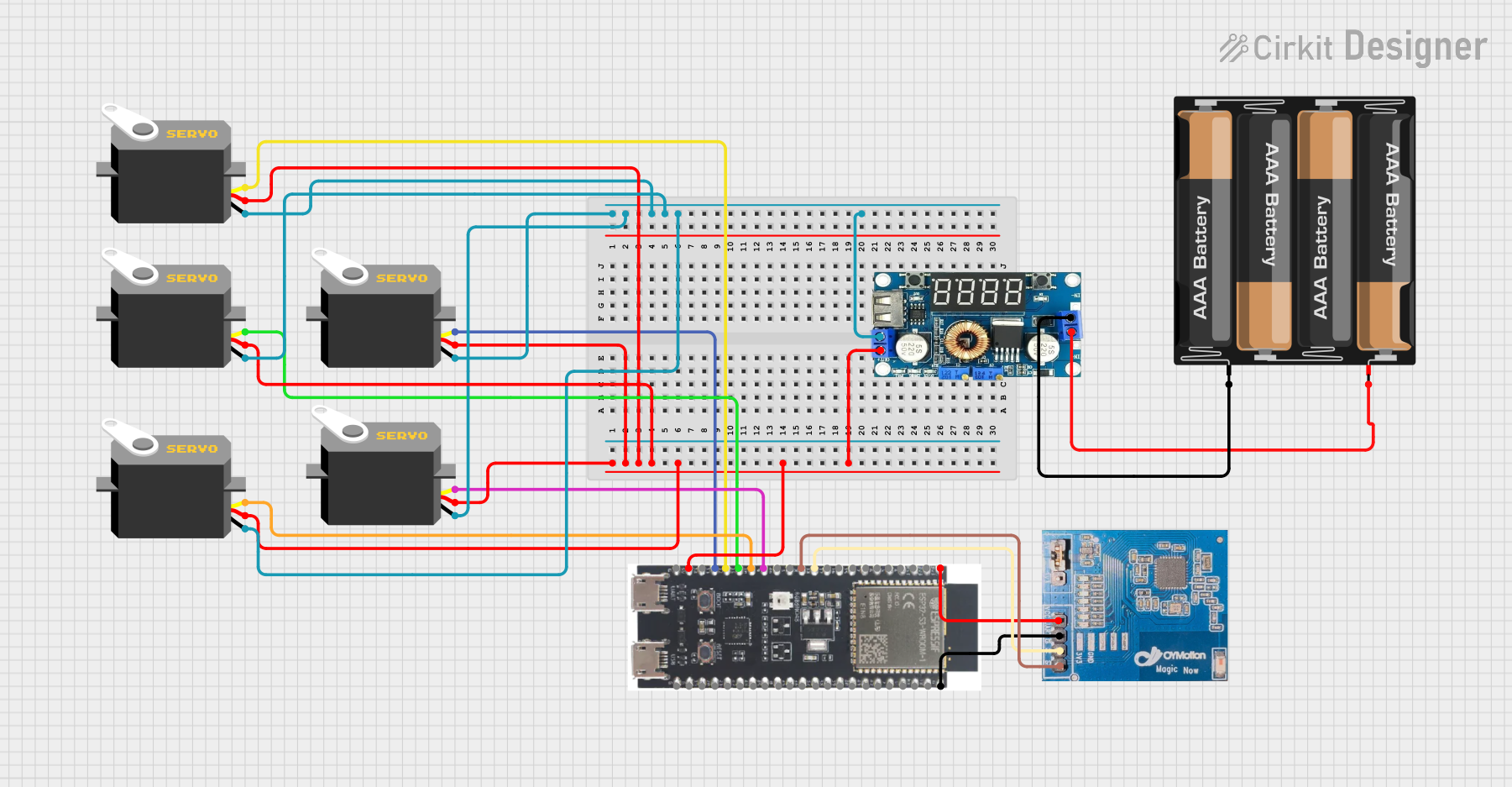
This circuit is a servo control system powered by a 4 x AAA battery pack, regulated by a step-down DC regulator. An ESP32-S3 microcontroller controls five servos and communicates with a gForceJoint UART sensor, enabling precise servo movements based on sensor inputs.
Open Project in Cirkit DesignerBluetooth-Controlled Robotic Vehicle with Arduino and Servo-Gearmotor Actuation
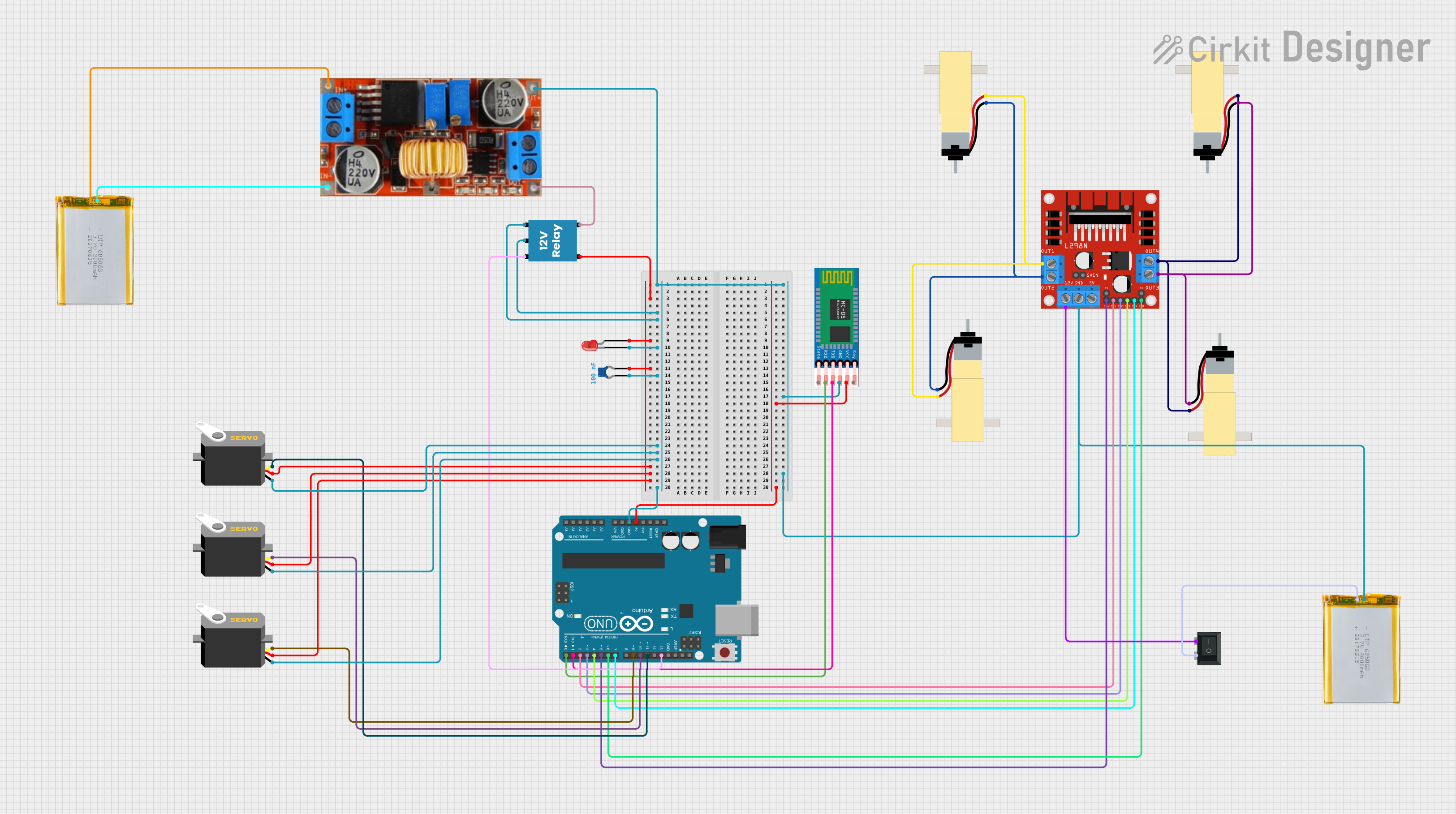
This circuit appears to be a remote-controlled robotic system with multiple servos and gearmotors, likely for movement and manipulation. An Arduino UNO microcontroller is used to control the servos and gearmotors via a L298N motor driver, and it interfaces with an HC-05 Bluetooth module for wireless communication. The system is powered by batteries, with a step-down converter to regulate voltage, and includes a relay and LED for power control and indication.
Open Project in Cirkit DesignerArduino-Controlled Robotic System with Bluetooth Interface and Motorized Actuators
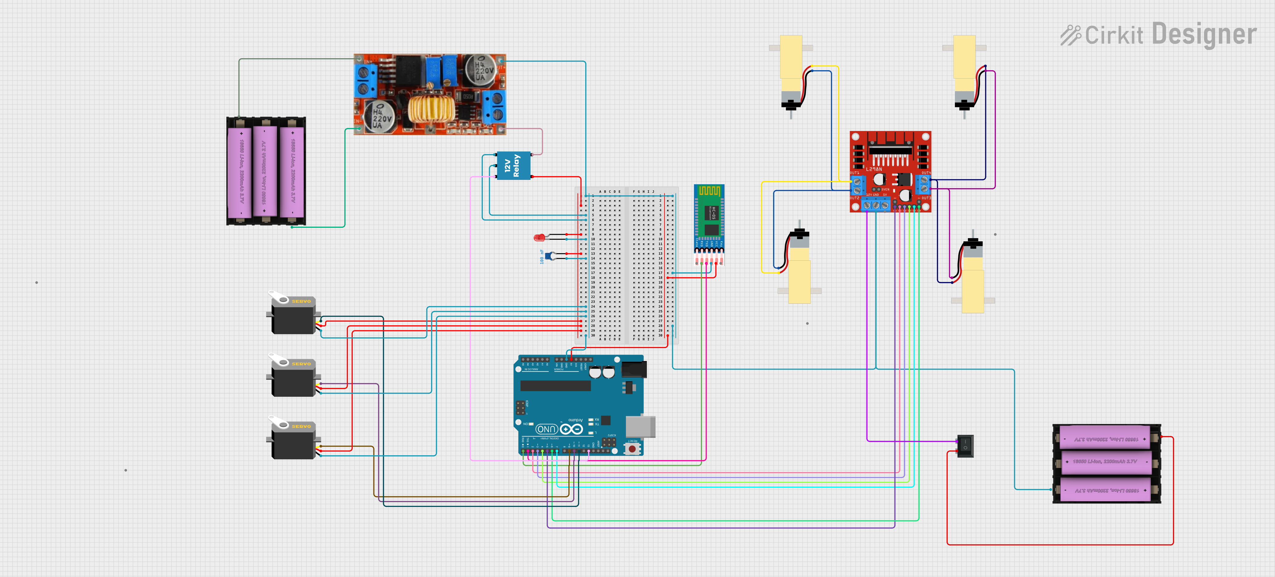
This circuit appears to be a remote-controlled robotic system with multiple servos and DC gearmotors, likely for movement and manipulation. An Arduino UNO microcontroller is used to control the servos and motors via a L298N motor driver, and it interfaces with an HC-05 Bluetooth module for wireless communication. Power management is handled by a Li-ion battery connected through a rocker switch and a step-down converter, with a relay and LED indicating the system's power status.
Open Project in Cirkit DesignerExplore Projects Built with Barrier bar servo motor
Bus Servo Controlled Robotic System with Power Module
This circuit controls multiple high-torque bus servos using a bus servo adaptor, which is powered by a 6-channel power module. The servos receive their control signals and power through the adaptor, enabling synchronized movement for applications requiring precise and powerful actuation.
Open Project in Cirkit DesignerBattery-Powered ESP32-S3 Controlled Servo System with gForceJoint UART
This circuit is a servo control system powered by a 4 x AAA battery pack, regulated by a step-down DC regulator. An ESP32-S3 microcontroller controls five servos and communicates with a gForceJoint UART sensor, enabling precise servo movements based on sensor inputs.
Open Project in Cirkit DesignerBluetooth-Controlled Robotic Vehicle with Arduino and Servo-Gearmotor Actuation
This circuit appears to be a remote-controlled robotic system with multiple servos and gearmotors, likely for movement and manipulation. An Arduino UNO microcontroller is used to control the servos and gearmotors via a L298N motor driver, and it interfaces with an HC-05 Bluetooth module for wireless communication. The system is powered by batteries, with a step-down converter to regulate voltage, and includes a relay and LED for power control and indication.
Open Project in Cirkit DesignerArduino-Controlled Robotic System with Bluetooth Interface and Motorized Actuators
This circuit appears to be a remote-controlled robotic system with multiple servos and DC gearmotors, likely for movement and manipulation. An Arduino UNO microcontroller is used to control the servos and motors via a L298N motor driver, and it interfaces with an HC-05 Bluetooth module for wireless communication. Power management is handled by a Li-ion battery connected through a rocker switch and a step-down converter, with a relay and LED indicating the system's power status.
Open Project in Cirkit DesignerCommon Applications:
- Parking lot barrier systems
- Toll gate automation
- Security checkpoints
- Industrial access control systems
Technical Specifications
Key Technical Details:
| Parameter | Value |
|---|---|
| Operating Voltage | 4.8V - 6.0V |
| Stall Torque | 10 kg·cm @ 6.0V |
| Operating Speed | 0.15 sec/60° @ 6.0V |
| Control Signal | PWM (Pulse Width Modulation) |
| Angular Range | 0° to 180° |
| Dead Band Width | 10 µs |
| Operating Temperature | -10°C to 50°C |
| Weight | 55 grams |
| Dimensions | 40mm x 20mm x 40mm |
Pin Configuration:
| Pin Number | Pin Name | Description |
|---|---|---|
| 1 | Signal (PWM) | Receives the PWM signal to control the motor. |
| 2 | VCC | Power supply input (4.8V - 6.0V). |
| 3 | GND | Ground connection for the motor. |
Usage Instructions
How to Use the Barrier Bar Servo Motor in a Circuit:
- Power Supply: Connect the VCC pin to a regulated 5V power source. Ensure the power supply can provide sufficient current (at least 2A) to handle peak loads.
- Signal Input: Connect the Signal pin to a microcontroller or servo driver capable of generating PWM signals. For example, an Arduino UNO can be used to control the motor.
- Grounding: Connect the GND pin to the ground of the power supply and the microcontroller to ensure a common reference point.
- Mounting: Secure the servo motor to the barrier bar mechanism using appropriate brackets or mounts. Ensure the motor shaft is aligned with the barrier bar for smooth operation.
Important Considerations:
- PWM Signal: The PWM signal determines the angular position of the servo. A pulse width of 1ms corresponds to 0°, 1.5ms to 90°, and 2ms to 180°.
- Load Capacity: Do not exceed the motor's torque rating to avoid damage.
- Power Supply: Use a stable power source to prevent voltage drops that could affect performance.
- Environmental Conditions: Protect the motor from extreme temperatures and moisture for outdoor applications.
Example Code for Arduino UNO:
#include <Servo.h> // Include the Servo library

Servo barrierServo; // Create a Servo object to control the motor

void setup() {
  barrierServo.attach(9); // Attach the servo to pin 9 on the Arduino
}

void loop() {
  // Open the barrier (move to 90 degrees)
  barrierServo.write(90); // Set servo position to 90 degrees
  delay(5000); // Keep the barrier open for 5 seconds

  // Close the barrier (move back to 0 degrees)
  barrierServo.write(0); // Set servo position to 0 degrees
  delay(5000); // Keep the barrier closed for 5 seconds
}
Note: Adjust the delay values and angles as needed for your specific application.
Troubleshooting and FAQs
Common Issues and Solutions:
Motor Not Moving:
- Cause: No PWM signal or incorrect wiring.
- Solution: Verify the Signal pin is connected to the correct microcontroller pin and that the PWM signal is being generated.
Erratic Movement:
- Cause: Insufficient power supply or electrical noise.
- Solution: Use a stable power source and add decoupling capacitors near the motor.
Overheating:
- Cause: Excessive load or prolonged operation at high torque.
- Solution: Reduce the load on the motor or allow cooling periods during operation.
Limited Angular Movement:
- Cause: Incorrect PWM signal range.
- Solution: Ensure the PWM signal pulse width is within the 1ms to 2ms range.
FAQs:
Q: Can this motor be used for continuous rotation?
- A: No, this is a positional servo motor designed for angular control, not continuous rotation.
Q: What happens if I exceed the torque rating?
- A: Exceeding the torque rating can damage the motor's internal gears or cause overheating.
Q: Can I use a 12V power supply?
- A: No, the motor is designed for a maximum of 6V. Using a higher voltage can permanently damage the motor.
Q: How do I protect the motor in outdoor environments?
- A: Use a weatherproof enclosure or apply a protective coating to shield the motor from moisture and dust.