Cirkit Designer Logo
Cirkit Designer
Your all-in-one circuit design IDE
Home / 
Component Documentation

How to Use USB C to 2 fils: Examples, Pinouts, and Specs

Image of USB C to 2 fils
Cirkit Designer LogoDesign with USB C to 2 fils in Cirkit Designer

Introduction

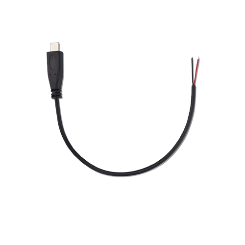
The USB-C to 2 Wires Adapter is a versatile component designed to split a USB-C connection into two separate wires. This adapter is commonly used for power delivery or data transfer applications, making it an essential tool for various electronic projects. Whether you are powering a device or transferring data, this adapter provides a simple and effective solution.

Explore Projects Built with USB C to 2 fils

Use Cirkit Designer to design, explore, and prototype these projects online. Some projects support real-time simulation. Click "Open Project" to start designing instantly!
Dual Hub Motor Control System with USB to TTL Interface and Relay Switching
Image of Hub Motor & servo motor Connection: A project utilizing USB C to 2 fils in a practical application
This circuit is designed to control two hub motors using a HUB driver, powered by a DC-DC converter and a power module. The USB to TTL converter allows for communication with the HUB driver, and a 5V relay module is used to switch the motors on and off.
Cirkit Designer LogoOpen Project in Cirkit Designer
USB Power Supply with Overcurrent Protection
Image of USB Charging port: A project utilizing USB C to 2 fils in a practical application
This circuit is designed to step down voltage from a 12V battery to a lower voltage suitable for USB devices. It includes a buck converter connected to the battery through a fuse and fuse holder for overcurrent protection. The output of the buck converter is connected to a USB female port, providing a regulated power supply for USB-powered devices.
Cirkit Designer LogoOpen Project in Cirkit Designer
USB-Powered Pushbutton Controlled LED Circuit
Image of oppgv. 10: A project utilizing USB C to 2 fils in a practical application
This circuit consists of a USB power converter supplying power to three pushbuttons, each connected to a corresponding red LED. When a button is pressed, it closes the circuit for its associated LED, causing the LED to light up. The common ground for the circuit is provided through a 40-pin connector, which also serves as an interface for the pushbuttons' inputs and the LEDs' cathodes.
Cirkit Designer LogoOpen Project in Cirkit Designer
Battery-Powered USB Charger with LED Indicator and DC Motor
Image of Copy of Hand Crank mobile charger : A project utilizing USB C to 2 fils in a practical application
This circuit converts AC power to DC using a bridge rectifier and regulates the voltage to 5V with a 7805 voltage regulator. It powers a USB port and indicates power status with an LED, while also providing a charging interface through a multi-charging cable.
Cirkit Designer LogoOpen Project in Cirkit Designer

Explore Projects Built with USB C to 2 fils

Use Cirkit Designer to design, explore, and prototype these projects online. Some projects support real-time simulation. Click "Open Project" to start designing instantly!
Image of Hub Motor & servo motor Connection: A project utilizing USB C to 2 fils in a practical application
Dual Hub Motor Control System with USB to TTL Interface and Relay Switching
This circuit is designed to control two hub motors using a HUB driver, powered by a DC-DC converter and a power module. The USB to TTL converter allows for communication with the HUB driver, and a 5V relay module is used to switch the motors on and off.
Cirkit Designer LogoOpen Project in Cirkit Designer
Image of USB Charging port: A project utilizing USB C to 2 fils in a practical application
USB Power Supply with Overcurrent Protection
This circuit is designed to step down voltage from a 12V battery to a lower voltage suitable for USB devices. It includes a buck converter connected to the battery through a fuse and fuse holder for overcurrent protection. The output of the buck converter is connected to a USB female port, providing a regulated power supply for USB-powered devices.
Cirkit Designer LogoOpen Project in Cirkit Designer
Image of oppgv. 10: A project utilizing USB C to 2 fils in a practical application
USB-Powered Pushbutton Controlled LED Circuit
This circuit consists of a USB power converter supplying power to three pushbuttons, each connected to a corresponding red LED. When a button is pressed, it closes the circuit for its associated LED, causing the LED to light up. The common ground for the circuit is provided through a 40-pin connector, which also serves as an interface for the pushbuttons' inputs and the LEDs' cathodes.
Cirkit Designer LogoOpen Project in Cirkit Designer
Image of Copy of Hand Crank mobile charger : A project utilizing USB C to 2 fils in a practical application
Battery-Powered USB Charger with LED Indicator and DC Motor
This circuit converts AC power to DC using a bridge rectifier and regulates the voltage to 5V with a 7805 voltage regulator. It powers a USB port and indicates power status with an LED, while also providing a charging interface through a multi-charging cable.
Cirkit Designer LogoOpen Project in Cirkit Designer

Common Applications and Use Cases

  • Power Delivery: Supplying power to devices that require a specific voltage and current.
  • Data Transfer: Connecting devices for data communication.
  • Prototyping: Useful in breadboard and prototyping environments for easy connections.
  • DIY Projects: Ideal for custom electronic projects and modifications.

Technical Specifications

Key Technical Details

Parameter Specification
Connector Type USB-C
Output Wires 2 (typically red and black)
Voltage Rating Up to 20V
Current Rating Up to 3A
Data Transfer USB 2.0 or USB 3.0 compatible
Wire Gauge 22 AWG
Length Varies (typically 15-30 cm)

Pin Configuration and Descriptions

Pin Number USB-C Pin Wire Color Description
1 VBUS Red Power (5V to 20V)
2 GND Black Ground

Usage Instructions

How to Use the Component in a Circuit

  1. Identify the Wires:

    • The red wire is typically the power wire (VBUS).
    • The black wire is the ground wire (GND).
  2. Connecting to a Power Source:

    • Connect the red wire to the positive terminal of your power source.
    • Connect the black wire to the ground terminal of your power source.
  3. Connecting to a Device:

    • Ensure the device's power requirements match the adapter's specifications.
    • Connect the red wire to the device's power input.
    • Connect the black wire to the device's ground.

Important Considerations and Best Practices

  • Voltage and Current Ratings: Ensure the voltage and current ratings of the adapter match the requirements of your device.
  • Polarity: Double-check the polarity of the connections to avoid damaging your device.
  • Insulation: Properly insulate the connections to prevent short circuits.
  • Heat Dissipation: Ensure adequate ventilation if the adapter is used for high-current applications.

Troubleshooting and FAQs

Common Issues Users Might Face

  1. No Power Delivery:

    • Solution: Check the connections and ensure the power source is functioning correctly. Verify that the voltage and current ratings are within the adapter's specifications.
  2. Overheating:

    • Solution: Ensure the adapter is not exceeding its current rating. Provide adequate ventilation and consider using a heat sink if necessary.
  3. Data Transfer Issues:

    • Solution: Verify that the adapter is compatible with the data transfer standards (USB 2.0 or USB 3.0). Check the connections and ensure the wires are not damaged.

Solutions and Tips for Troubleshooting

  • Multimeter Testing: Use a multimeter to check the voltage and continuity of the connections.
  • Visual Inspection: Inspect the wires and connections for any visible damage or loose connections.
  • Component Compatibility: Ensure all components in the circuit are compatible with the adapter's specifications.

Example Code for Arduino UNO

If you are using the USB-C to 2 Wires Adapter to power an Arduino UNO, you can use the following code to test the setup:

// Simple Blink Example
// This code will blink the onboard LED on the Arduino UNO

void setup() {
  pinMode(LED_BUILTIN, OUTPUT); // Set the LED pin as an output
}

void loop() {
  digitalWrite(LED_BUILTIN, HIGH); // Turn the LED on
  delay(1000);                     // Wait for 1 second
  digitalWrite(LED_BUILTIN, LOW);  // Turn the LED off
  delay(1000);                     // Wait for 1 second
}

Ensure the USB-C to 2 Wires Adapter is properly connected to the Arduino UNO's power input (5V and GND) before uploading the code.


This documentation provides a comprehensive guide to using the USB-C to 2 Wires Adapter, ensuring both beginners and experienced users can effectively utilize this component in their projects.