How to Use Microcontroller : Examples, Pinouts, and Specs
Introduction
The AT89C51 is a compact and versatile microcontroller designed for embedded systems. Manufactured by Microcontroller, this device integrates a processor, memory, and input/output peripherals into a single chip, making it ideal for controlling specific operations in various applications. Its robust architecture and ease of use make it a popular choice for both beginners and experienced developers.
Explore Projects Built with Microcontroller
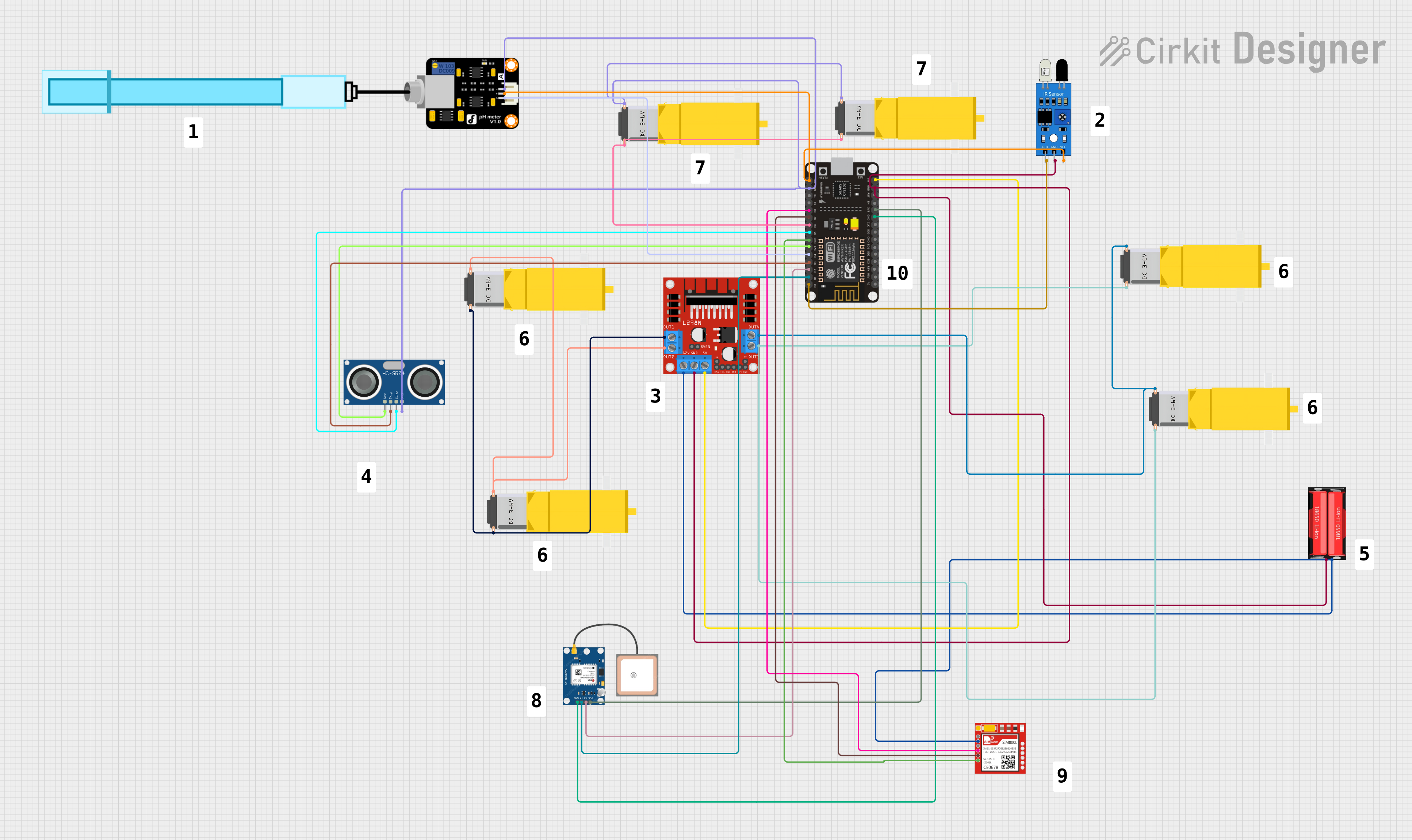
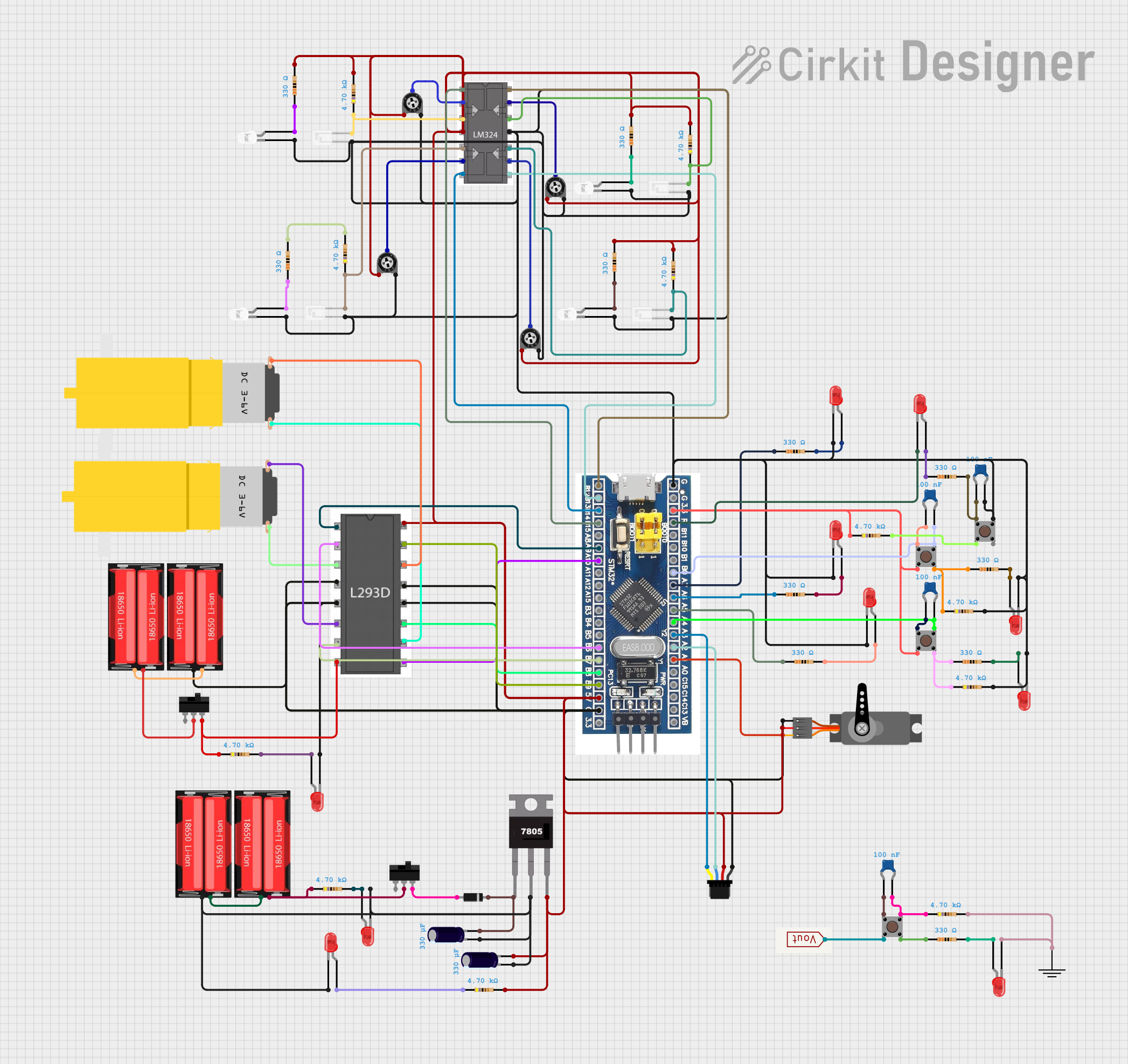

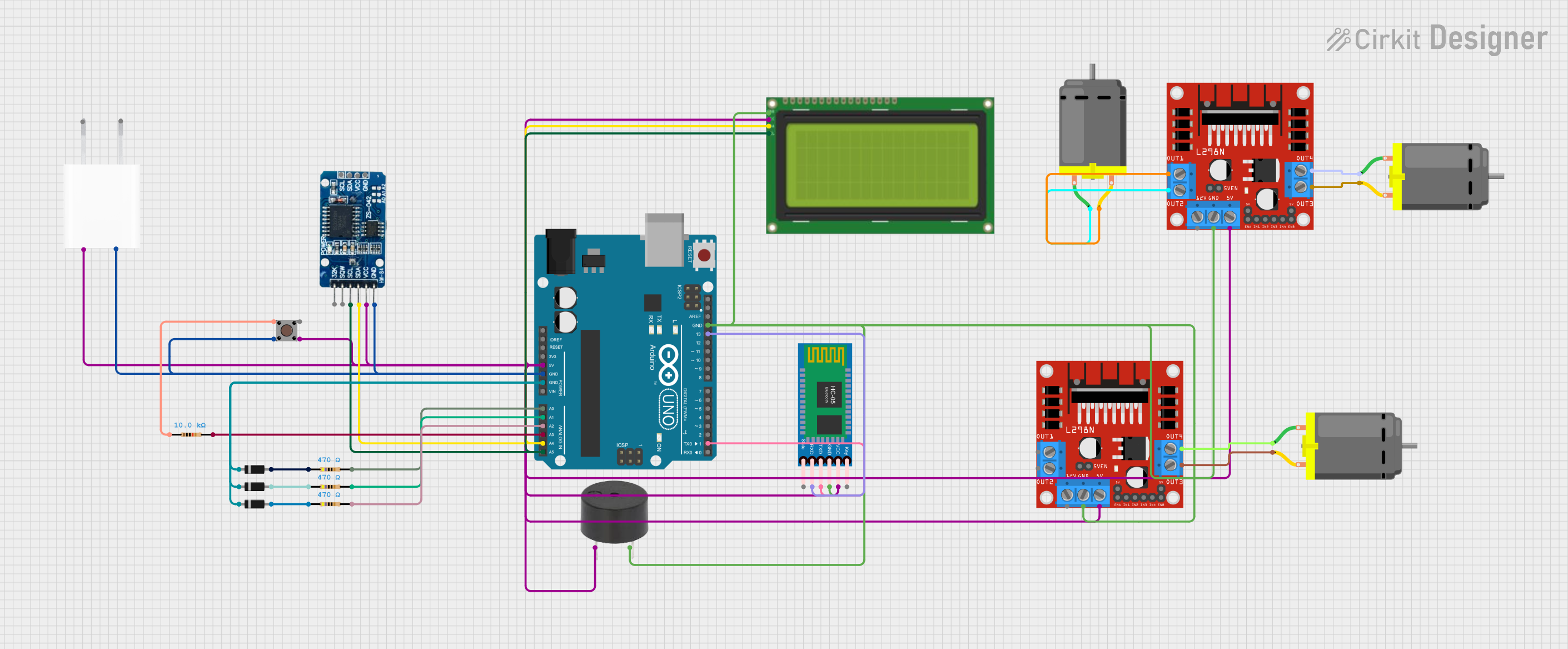
Explore Projects Built with Microcontroller
Common Applications and Use Cases
- Home automation systems
- Industrial control systems
- Consumer electronics
- Robotics and mechatronics
- Data acquisition systems
- Educational projects and prototyping
Technical Specifications
The AT89C51 microcontroller is based on the 8051 architecture and offers the following key specifications:
| Parameter | Value |
|---|---|
| Processor Core | 8-bit 8051 |
| Operating Voltage | 4.0V to 5.5V |
| Maximum Clock Frequency | 24 MHz |
| Flash Memory | 4 KB |
| RAM | 128 bytes |
| I/O Ports | 32 (4 ports, each with 8 pins) |
| Timers/Counters | 2 (16-bit each) |
| Serial Communication | 1 UART |
| Interrupt Sources | 6 |
| Power Consumption | Low power consumption in idle and power-down modes |
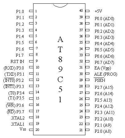
Pin Configuration and Descriptions
The AT89C51 comes in a 40-pin Dual Inline Package (DIP). Below is the pin configuration:
| Pin Number | Pin Name | Description |
|---|---|---|
| 1-8 | P1.0-P1.7 | Port 1: General-purpose I/O pins |
| 9 | RST | Reset: Active high reset input |
| 10-17 | P3.0-P3.7 | Port 3: I/O pins with alternate functions (e.g., UART, interrupts) |
| 18-19 | XTAL2, XTAL1 | Crystal oscillator pins for external clock input |
| 20 | GND | Ground |
| 21-28 | P2.0-P2.7 | Port 2: General-purpose I/O pins or high-order address bus |
| 29 | PSEN | Program Store Enable: Used for external program memory |
| 30 | ALE/PROG | Address Latch Enable: Latches low-order address bus |
| 31 | EA/VPP | External Access: Enables external memory access |
| 32-39 | P0.0-P0.7 | Port 0: General-purpose I/O pins or low-order address/data bus |
| 40 | VCC | Power supply (4.0V to 5.5V) |
Usage Instructions
How to Use the AT89C51 in a Circuit
- Power Supply: Connect the VCC pin to a 5V power source and the GND pin to ground.
- Clock Configuration: Attach a crystal oscillator (typically 12 MHz) between XTAL1 and XTAL2, along with two 33pF capacitors to stabilize the clock signal.
- Reset Circuit: Connect a 10 µF capacitor and a 10 kΩ resistor to the RST pin to ensure proper reset functionality.
- I/O Configuration: Use the I/O ports (P0, P1, P2, P3) for interfacing with external devices such as LEDs, sensors, or motors.
- Programming: Use an external programmer to load your program into the microcontroller's flash memory.
Important Considerations and Best Practices
- Ensure the operating voltage does not exceed 5.5V to avoid damaging the microcontroller.
- Use decoupling capacitors (e.g., 0.1 µF) near the power pins to reduce noise and improve stability.
- Avoid leaving unused pins floating; connect them to ground or configure them as outputs.
- For UART communication, connect the TXD and RXD pins (P3.1 and P3.0) to the corresponding pins of your serial device.
Example: Interfacing with an Arduino UNO
The AT89C51 can communicate with an Arduino UNO via UART. Below is an example Arduino code to send data to the AT89C51:
// Arduino code to send data to AT89C51 via UART
void setup() {
  Serial.begin(9600); // Initialize serial communication at 9600 baud
}

void loop() {
  Serial.println("Hello, AT89C51!"); // Send a message to the AT89C51
  delay(1000); // Wait for 1 second before sending the next message
}
Troubleshooting and FAQs
Common Issues and Solutions
Microcontroller Not Responding
- Cause: Incorrect power supply or clock configuration.
- Solution: Verify the power connections and ensure the crystal oscillator is properly connected.
Program Not Executing
- Cause: Improper programming or corrupted flash memory.
- Solution: Reprogram the microcontroller using a reliable programmer and verify the code.
UART Communication Fails
- Cause: Mismatched baud rates or incorrect wiring.
- Solution: Ensure both devices use the same baud rate and check the TXD/RXD connections.
I/O Pins Not Functioning
- Cause: Pins configured incorrectly or left floating.
- Solution: Verify the pin configuration in your code and connect unused pins to ground.
FAQs
Q: Can the AT89C51 be used with external memory?
A: Yes, the AT89C51 supports external program and data memory via the PSEN and EA pins.
Q: What is the maximum clock frequency supported?
A: The AT89C51 supports a maximum clock frequency of 24 MHz.
Q: How do I reduce power consumption?
A: Use the idle or power-down modes to minimize power consumption when the microcontroller is not actively processing.
Q: Can I use the AT89C51 for real-time applications?
A: Yes, the AT89C51 is suitable for real-time applications, but ensure the timing requirements are within its processing capabilities.