How to Use 60x60x20 Fan 24V: Examples, Pinouts, and Specs
Introduction
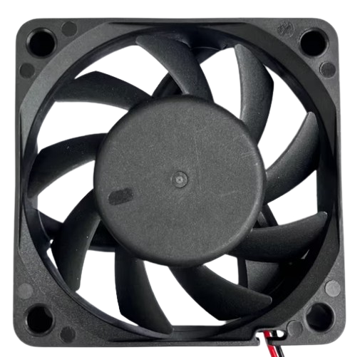
The 60x60x20 Fan 24V is a compact axial fan designed for efficient cooling in electronic and industrial applications. With dimensions of 60mm x 60mm x 20mm and a 24V operating voltage, this fan is ideal for dissipating heat and maintaining optimal operating temperatures in devices such as power supplies, 3D printers, computer systems, and other heat-sensitive equipment. Its small size and reliable performance make it a popular choice for thermal management in confined spaces.
Explore Projects Built with 60x60x20 Fan 24V


Explore Projects Built with 60x60x20 Fan 24V
Common Applications and Use Cases
- Cooling electronic components in power supplies and enclosures
- Thermal management in 3D printers and CNC machines
- Heat dissipation in computer systems and servers
- Ventilation in small appliances and industrial control panels
Technical Specifications
The following table outlines the key technical specifications of the 60x60x20 Fan 24V:
| Parameter | Specification |
|---|---|
| Dimensions | 60mm x 60mm x 20mm |
| Operating Voltage | 24V DC |
| Current Consumption | ~0.1A (varies by model) |
| Power Consumption | ~2.4W |
| Airflow | ~20-25 CFM (Cubic Feet per Minute) |
| Noise Level | ~25-30 dBA |
| Bearing Type | Sleeve or Ball Bearing (varies) |
| Connector Type | 2-pin or 3-pin (depending on model) |
| Operating Temperature | -10°C to +70°C |
| Lifespan | ~30,000 to 50,000 hours |
Pin Configuration and Descriptions
The fan typically comes with a 2-pin or 3-pin connector. The pin configuration is as follows:
2-Pin Connector
| Pin Number | Wire Color | Description |
|---|---|---|
| 1 | Red | Positive (+24V DC) |
| 2 | Black | Ground (GND) |
3-Pin Connector
| Pin Number | Wire Color | Description |
|---|---|---|
| 1 | Red | Positive (+24V DC) |
| 2 | Black | Ground (GND) |
| 3 | Yellow | Tachometer Signal (optional) |
Usage Instructions
How to Use the 60x60x20 Fan 24V in a Circuit
- Power Supply: Ensure you have a 24V DC power source capable of supplying at least 0.1A of current.
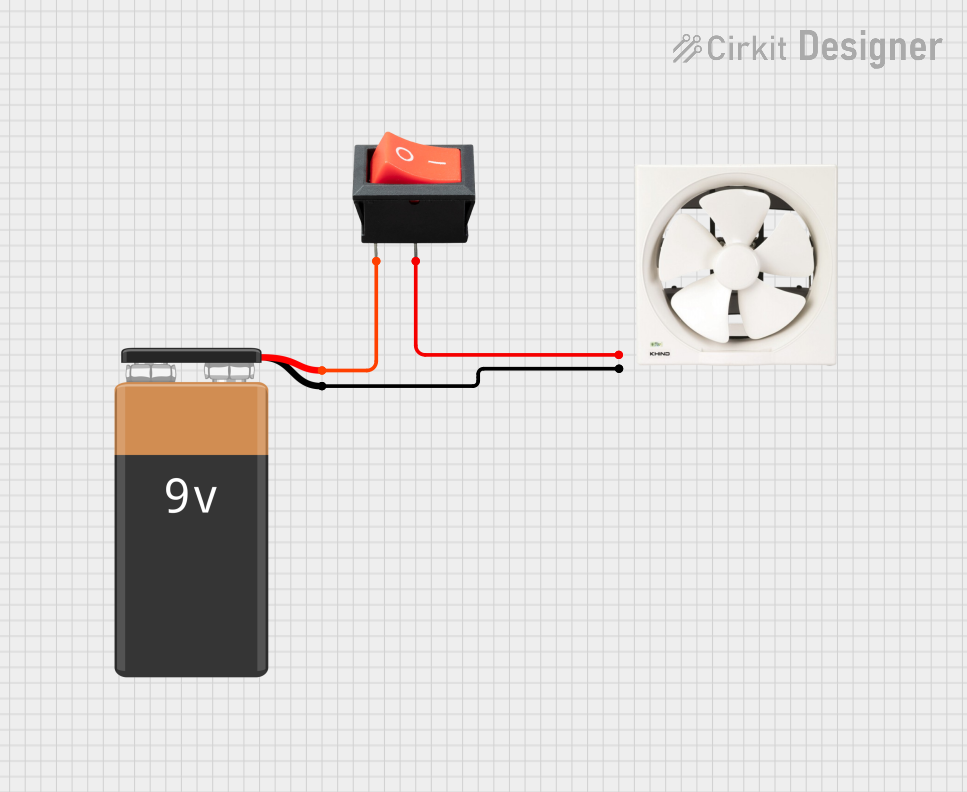
- Wiring:
- For a 2-pin fan, connect the red wire to the positive terminal of the power supply and the black wire to the ground terminal.
- For a 3-pin fan, connect the red and black wires as above. The yellow wire can be connected to a microcontroller or monitoring circuit to read the fan's speed (tachometer signal).
- Mounting: Secure the fan using screws or adhesive mounts. Ensure proper airflow direction by checking the arrow markings on the fan housing.
- Testing: Power on the circuit and verify that the fan spins smoothly and provides adequate airflow.
Important Considerations and Best Practices
- Voltage Compatibility: Do not exceed the rated 24V DC input to avoid damaging the fan.
- Airflow Direction: The fan's airflow direction is typically indicated by arrows on the housing. Ensure the fan is oriented correctly for optimal cooling.
- Noise Reduction: Use rubber mounts or grommets to minimize vibration and noise.
- Maintenance: Periodically clean the fan blades to remove dust and debris, which can reduce efficiency and lifespan.
- Tachometer Signal: If using the 3-pin version, connect the yellow wire to a microcontroller (e.g., Arduino) to monitor the fan's speed.
Example: Connecting to an Arduino UNO
If you are using the 3-pin version of the fan and want to monitor its speed, you can connect the tachometer signal to an Arduino UNO. Below is an example code snippet:
// Example code to read the tachometer signal from a 60x60x20 Fan 24V
// Connect the fan's yellow wire to Arduino pin 2 (interrupt pin)

const int tachPin = 2;  // Tachometer signal pin
volatile int fanRPM = 0;  // Variable to store fan speed in RPM
volatile int pulseCount = 0;  // Count of tachometer pulses

void setup() {
  pinMode(tachPin, INPUT_PULLUP);  // Set tachometer pin as input
  attachInterrupt(digitalPinToInterrupt(tachPin), countPulses, FALLING);
  Serial.begin(9600);  // Initialize serial communication
}

void loop() {
  delay(1000);  // Wait for 1 second
  noInterrupts();  // Disable interrupts to calculate RPM
  fanRPM = (pulseCount * 60) / 2;  // Calculate RPM (2 pulses per revolution)
  pulseCount = 0;  // Reset pulse count
  interrupts();  // Re-enable interrupts
  Serial.print("Fan Speed: ");
  Serial.print(fanRPM);
  Serial.println(" RPM");
}

void countPulses() {
  pulseCount++;  // Increment pulse count on each falling edge
}
Troubleshooting and FAQs
Common Issues and Solutions
Fan Not Spinning:
- Cause: Insufficient voltage or incorrect wiring.
- Solution: Verify the power supply provides 24V DC and check the wiring connections.
Excessive Noise:
- Cause: Dust buildup, loose mounting, or worn bearings.
- Solution: Clean the fan blades, tighten mounting screws, or replace the fan if bearings are worn.
Low Airflow:
- Cause: Obstructions or incorrect orientation.
- Solution: Remove any obstructions and ensure the fan is mounted with the correct airflow direction.
Tachometer Signal Not Working:
- Cause: Incorrect connection or incompatible microcontroller.
- Solution: Verify the yellow wire is connected to a digital input pin and ensure the microcontroller supports interrupt-based signal reading.
FAQs
Q1: Can I use this fan with a 12V power supply?
A1: No, the fan is designed for 24V DC operation. Using a lower voltage may result in reduced performance or failure to start.
Q2: How do I determine the airflow direction?
A2: The airflow direction is indicated by arrows on the fan housing. One arrow shows the airflow direction, and the other shows the blade rotation direction.
Q3: Can I control the fan speed?
A3: This fan does not have built-in PWM control. However, you can use an external PWM controller or a transistor circuit to modulate the voltage and control the speed.
Q4: What is the lifespan of this fan?
A4: The fan typically has a lifespan of 30,000 to 50,000 hours, depending on operating conditions and maintenance.