How to Use 5v Boost Converter: Examples, Pinouts, and Specs
Introduction
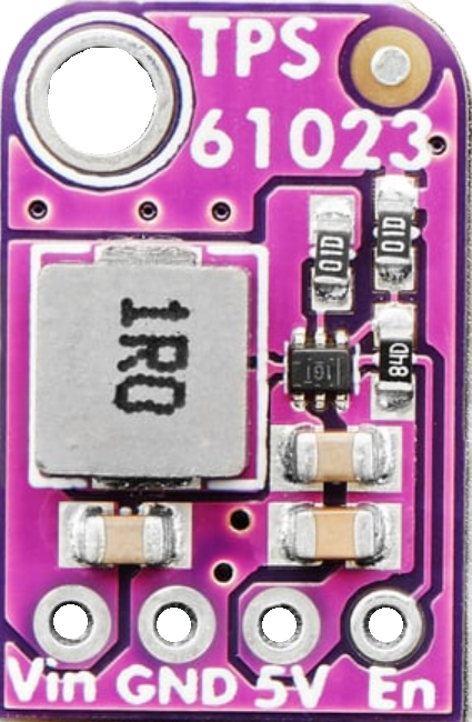
The 5V Boost Converter (Manufacturer: Adafruit, Part ID: TPS61023) is a DC-DC step-up converter designed to increase a lower input voltage to a stable 5V output. This component is ideal for powering devices that require a consistent 5V supply, even when the input voltage is lower, such as in battery-powered applications. Its compact design and high efficiency make it a popular choice for portable electronics, IoT devices, and embedded systems.
Explore Projects Built with 5v Boost Converter


Explore Projects Built with 5v Boost Converter
Common Applications
- Powering microcontrollers (e.g., Arduino, Raspberry Pi) from batteries
- Extending the life of single-cell Li-ion or alkaline batteries
- Portable USB-powered devices
- Wearable electronics
- Low-power IoT devices
Technical Specifications
The following table outlines the key technical details of the Adafruit TPS61023 5V Boost Converter:
| Parameter | Value |
|---|---|
| Input Voltage Range | 0.5V to 5.5V |
| Output Voltage | 5V (fixed) |
| Output Current | Up to 1A (depending on input voltage) |
| Efficiency | Up to 90% |
| Switching Frequency | 1.5 MHz |
| Operating Temperature | -40°C to +125°C |
| Dimensions | 17.8mm x 12.7mm x 4.5mm |
Pin Configuration and Descriptions
The 5V Boost Converter typically has the following pinout:
| Pin Name | Description |
|---|---|
| VIN | Input voltage pin. Connect to the power source (e.g., battery). |
| GND | Ground pin. Connect to the ground of the circuit. |
| VOUT | Output voltage pin. Provides the boosted 5V output. |
| EN | Enable pin. Pull high to enable the converter; pull low to disable it. |
| FB | Feedback pin. Used for internal voltage regulation (not typically user-altered). |
Usage Instructions
How to Use the 5V Boost Converter in a Circuit
Connect the Input Voltage (VIN):
- Attach the VIN pin to your power source, such as a single-cell Li-ion battery or a 2x AA battery pack.
- Ensure the input voltage is within the range of 0.5V to 5.5V.
Connect the Ground (GND):
- Connect the GND pin to the ground of your circuit.
Connect the Output Voltage (VOUT):
- Attach the VOUT pin to the device or circuit requiring a 5V power supply.
Enable the Converter:
- Pull the EN pin high (connect to VIN or a logic high signal) to enable the boost converter.
- To disable the converter, pull the EN pin low or leave it unconnected.
Add Decoupling Capacitors:
- Place a capacitor (e.g., 10µF) between VIN and GND to stabilize the input voltage.
- Place another capacitor (e.g., 22µF) between VOUT and GND to smooth the output voltage.
Important Considerations
- Input Voltage Limitations: Ensure the input voltage does not exceed 5.5V to avoid damaging the converter.
- Heat Dissipation: While the TPS61023 is efficient, it may generate heat under high load. Ensure proper ventilation or heat sinking if necessary.
- Load Current: The maximum output current depends on the input voltage. For example, at lower input voltages, the output current capability decreases.
- Noise Sensitivity: Use short, thick wires for connections to minimize noise and voltage drops.
Example: Using the 5V Boost Converter with an Arduino UNO
The following example demonstrates how to power an Arduino UNO using the 5V Boost Converter and a 3.7V Li-ion battery.
Circuit Connections
- Connect the battery's positive terminal to the VIN pin of the boost converter.
- Connect the battery's negative terminal to the GND pin of the boost converter.
- Connect the VOUT pin of the boost converter to the 5V pin of the Arduino UNO.
- Connect the GND pin of the boost converter to the GND pin of the Arduino UNO.
Arduino Code Example
// Example code to blink an LED on pin 13 of Arduino UNO
// This demonstrates the Arduino running on power supplied by the 5V Boost Converter.

void setup() {
  pinMode(13, OUTPUT); // Set pin 13 as an output pin
}

void loop() {
  digitalWrite(13, HIGH); // Turn the LED on
  delay(1000);            // Wait for 1 second
  digitalWrite(13, LOW);  // Turn the LED off
  delay(1000);            // Wait for 1 second
}
Troubleshooting and FAQs
Common Issues and Solutions
No Output Voltage:
- Cause: The EN pin is not pulled high.
- Solution: Ensure the EN pin is connected to VIN or a logic high signal.
Output Voltage is Unstable:
- Cause: Insufficient decoupling capacitors.
- Solution: Add capacitors (e.g., 10µF on VIN and 22µF on VOUT) to stabilize the voltage.
Excessive Heat:
- Cause: High load current or poor ventilation.
- Solution: Reduce the load current or improve airflow around the converter.
Low Efficiency:
- Cause: Input voltage is too close to the output voltage.
- Solution: Use a higher input voltage within the supported range for better efficiency.
FAQs
Q: Can I use the 5V Boost Converter with a 1.5V AA battery?
A: Yes, the TPS61023 can boost a 1.5V input to 5V. However, the output current will be limited due to the low input voltage.
Q: Is the converter suitable for powering USB devices?
A: Yes, as long as the device's current requirement does not exceed the converter's maximum output current (1A).
Q: Can I leave the EN pin unconnected?
A: No, leaving the EN pin unconnected may cause the converter to remain disabled. Pull it high to enable the converter.
Q: What happens if the input voltage exceeds 5.5V?
A: Exceeding 5.5V can damage the converter. Always ensure the input voltage stays within the specified range.
This concludes the documentation for the Adafruit TPS61023 5V Boost Converter.