How to Use CNC SHIELD V3: Examples, Pinouts, and Specs
Introduction
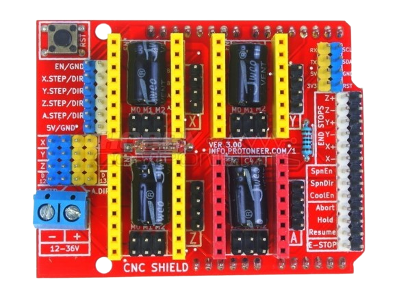
The CNC SHIELD V3, manufactured by INFO PROTONER (Part ID: CNC SHIELD), is a versatile control board designed for CNC machines, 3D printers, and laser engravers. It provides an efficient and compact solution for controlling stepper motors, endstops, and other peripherals. The shield is compatible with GRBL firmware and can be easily mounted on an Arduino UNO, making it a popular choice for DIY projects and professional applications alike.
Explore Projects Built with CNC SHIELD V3

Explore Projects Built with CNC SHIELD V3
Common Applications and Use Cases
- CNC milling machines
- 3D printers
- Laser engravers
- Plotters and drawing machines
- Robotics projects requiring precise motor control
Technical Specifications
The CNC SHIELD V3 is designed to simplify the control of stepper motors and other components in CNC and 3D printing applications. Below are its key technical details:
Key Technical Details
- Input Voltage: 12V to 36V DC (via external power supply for stepper motors)
- Logic Voltage: 5V (provided by the Arduino UNO)
- Stepper Motor Drivers Supported: A4988, DRV8825, or compatible drivers
- Number of Axes: 3 (X, Y, Z) with an optional 4th axis (A)
- Endstop Connections: 6 (2 per axis for X, Y, Z)
- Microstepping Support: Configurable via jumpers
- Firmware Compatibility: GRBL (open-source CNC firmware)
- Dimensions: 68mm x 53mm (fits standard Arduino UNO form factor)
Pin Configuration and Descriptions
The CNC SHIELD V3 has a straightforward pin layout for easy integration. Below is a detailed description of its pin configuration:
Stepper Motor Driver Pins
| Pin Name | Description |
|---|---|
| VMOT | Power input for stepper motors (12V-36V DC). |
| GND | Ground connection for stepper motor power supply. |
| STEP | Step pulse input for controlling motor steps. |
| DIR | Direction control input for stepper motors. |
| EN | Enable pin for activating or deactivating the driver. |
Endstop Pins
| Pin Name | Description |
|---|---|
| X+, X- | Endstop connections for the X-axis (positive and negative directions). |
| Y+, Y- | Endstop connections for the Y-axis (positive and negative directions). |
| Z+, Z- | Endstop connections for the Z-axis (positive and negative directions). |
Other Pins
| Pin Name | Description |
|---|---|
| Spindle Enable | Controls the spindle motor (on/off). |
| Coolant Enable | Controls the coolant system (on/off). |
| A Axis | Optional 4th axis stepper motor driver connections. |
Usage Instructions
The CNC SHIELD V3 is designed to be user-friendly and easy to integrate into CNC and 3D printing projects. Follow the steps below to use the shield effectively:
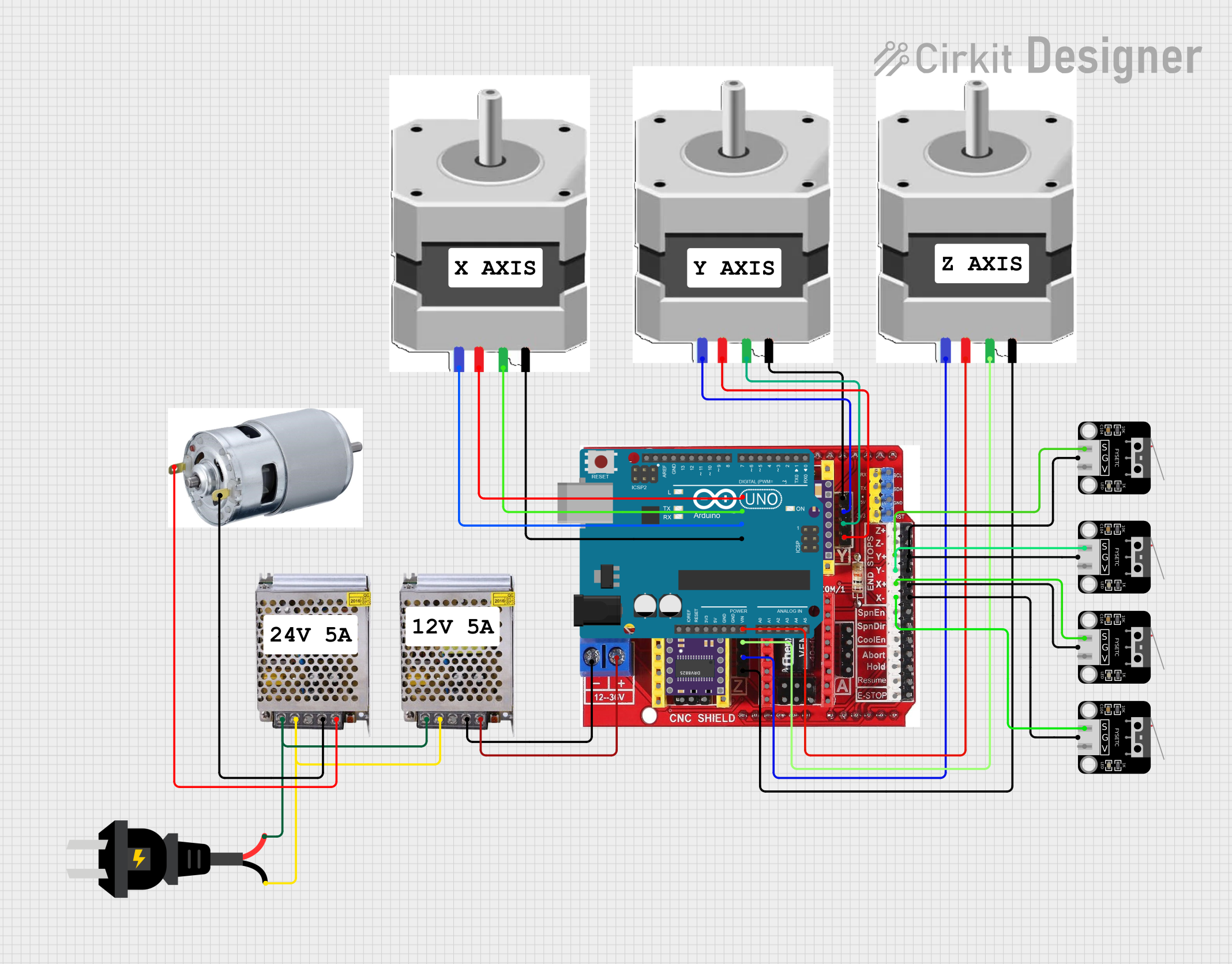
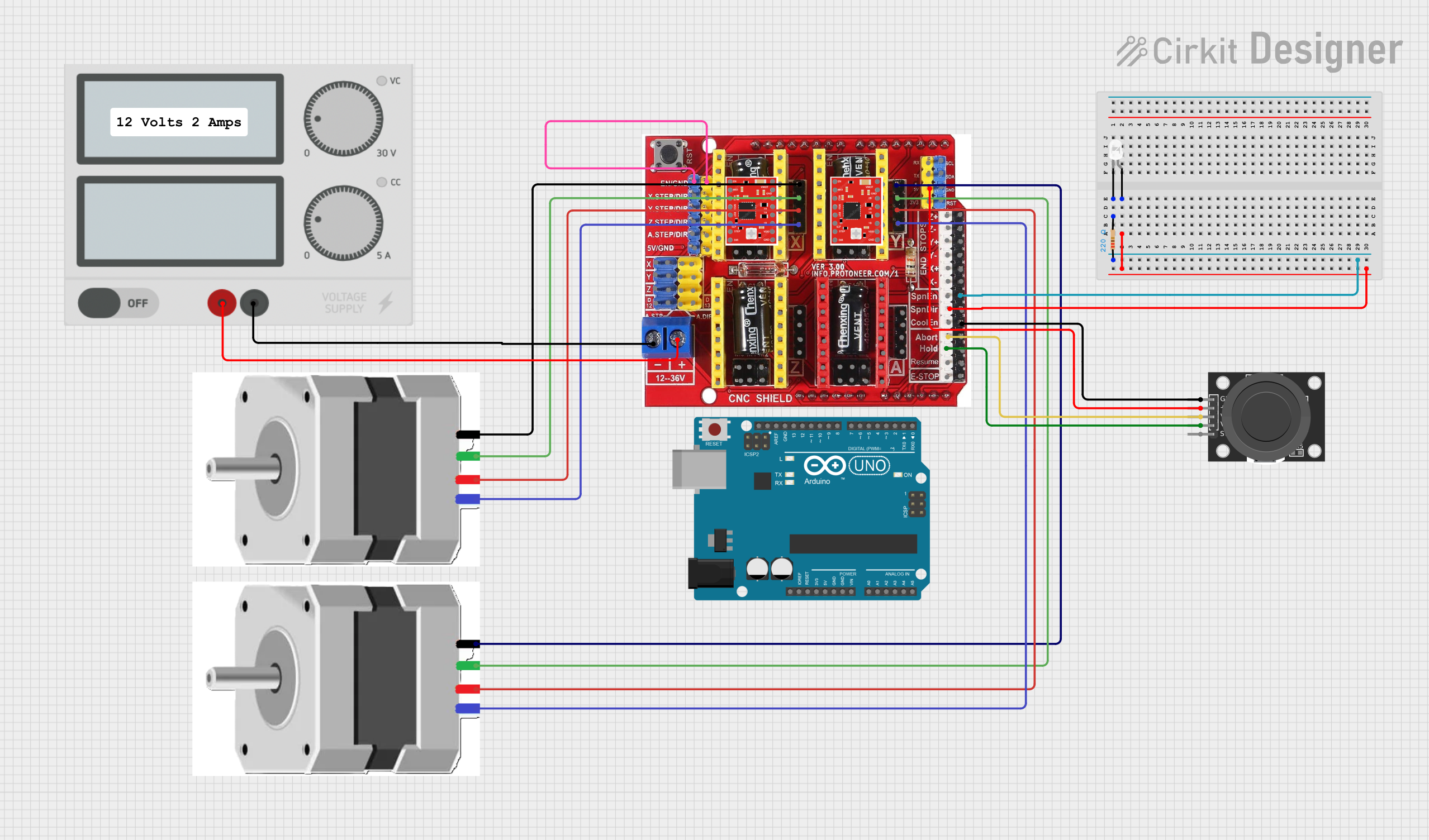
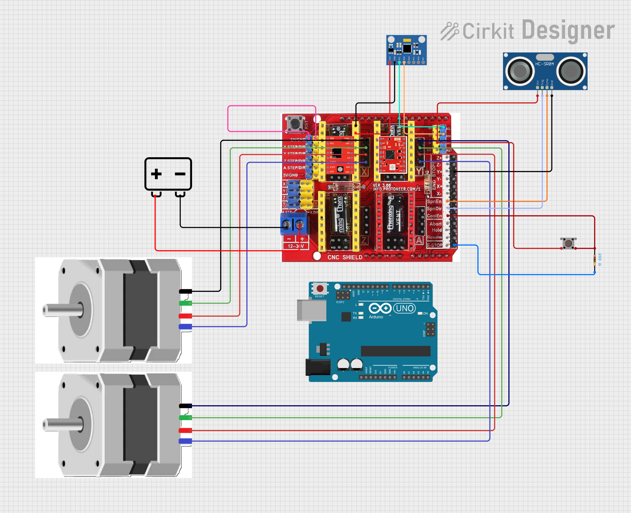
Step 1: Assembly and Connections
- Mount the Shield: Place the CNC SHIELD V3 on top of an Arduino UNO, ensuring the pins align correctly.
- Install Stepper Drivers: Insert A4988 or DRV8825 stepper motor drivers into the designated sockets. Ensure the orientation matches the markings on the shield.
- Connect Stepper Motors: Attach the stepper motors to the X, Y, Z, and (optional) A-axis motor connectors.
- Connect Endstops: Wire the endstop switches to the corresponding X+, X-, Y+, Y-, Z+, and Z- pins.
- Power the Shield: Connect a 12V-36V DC power supply to the VMOT and GND terminals for the stepper motors.
Step 2: Configure Microstepping
- Use the jumpers beneath each stepper driver socket to set the desired microstepping mode (e.g., full step, half step, 1/4 step, etc.).
- Refer to the stepper driver datasheet for the correct jumper configuration.
Step 3: Upload GRBL Firmware
- Download the GRBL firmware from its official repository.
- Open the GRBL firmware in the Arduino IDE.
- Select the correct board (Arduino UNO) and port in the Arduino IDE.
- Upload the firmware to the Arduino UNO.
Step 4: Test the Setup
- Use a GRBL-compatible control software (e.g., Universal Gcode Sender) to test the movement of the motors and the functionality of the endstops.
Example Code for Arduino UNO
Below is an example of how to control the CNC SHIELD V3 using GRBL firmware. Note that GRBL handles most of the low-level control, so this code is for uploading GRBL to the Arduino UNO.
// This example assumes you have downloaded the GRBL firmware.
// Follow these steps to upload GRBL to your Arduino UNO:

// 1. Open the GRBL firmware folder in the Arduino IDE.
// 2. Select the "grblUpload" sketch from the examples.
// 3. Ensure the correct board (Arduino UNO) and port are selected.
// 4. Click "Upload" to flash the firmware onto the Arduino UNO.

// Once uploaded, use a GRBL-compatible software to control the CNC SHIELD V3.
Important Considerations
- Always disconnect power before inserting or removing stepper drivers to avoid damage.
- Use heatsinks on stepper drivers to prevent overheating during operation.
- Ensure the power supply voltage matches the requirements of your stepper motors.
Troubleshooting and FAQs
Common Issues and Solutions
Stepper Motors Not Moving
- Cause: Incorrect wiring or loose connections.
- Solution: Double-check motor connections and ensure the stepper drivers are properly seated.
Overheating Stepper Drivers
- Cause: Insufficient cooling or incorrect current settings.
- Solution: Attach heatsinks to the drivers and adjust the current limit using the potentiometer on the driver.
Endstops Not Detected
- Cause: Miswired or faulty endstop switches.
- Solution: Verify the wiring and test the switches with a multimeter.
GRBL Not Responding
- Cause: Incorrect firmware upload or communication settings.
- Solution: Re-upload GRBL firmware and ensure the correct baud rate (115200) is set in the control software.
FAQs
Can I use the CNC SHIELD V3 with other Arduino boards?
- The shield is designed for the Arduino UNO but may work with other boards that have a similar pinout.
What stepper motors are compatible with the shield?
- The shield supports most bipolar stepper motors that operate within the voltage and current limits of the A4988 or DRV8825 drivers.
How do I enable the 4th axis (A)?
- Install a stepper driver in the A-axis socket and connect the motor. Configure GRBL to enable the 4th axis.
By following this documentation, you can effectively use the CNC SHIELD V3 in your projects. For further assistance, refer to the GRBL documentation or contact INFO PROTONER support.