Cirkit Designer Logo
Cirkit Designer
Your all-in-one circuit design IDE
Home / 
Component Documentation

How to Use Logic Level Shifter, 4-Channel, Bidirectional: Examples, Pinouts, and Specs

Image of Logic Level Shifter, 4-Channel, Bidirectional
Cirkit Designer LogoDesign with Logic Level Shifter, 4-Channel, Bidirectional in Cirkit Designer

Introduction

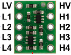
The Pololu Logic Level Shifter is a versatile device designed to facilitate the safe and efficient translation of voltage levels between different parts of a circuit. This component supports four channels and bidirectional communication, making it ideal for interfacing devices that operate at different voltage levels. Common applications include connecting 3.3V sensors to a 5V microcontroller, interfacing between different logic families, and enabling communication between devices with different voltage requirements.

Explore Projects Built with Logic Level Shifter, 4-Channel, Bidirectional

Use Cirkit Designer to design, explore, and prototype these projects online. Some projects support real-time simulation. Click "Open Project" to start designing instantly!
Logic Gate Experimentation Board with DIP Switch Control and LED Indicators
Image of Lab 4 Encoder: A project utilizing Logic Level Shifter, 4-Channel, Bidirectional in a practical application
This circuit is a digital logic demonstration setup using a 3-position DIP switch to control the logic states of a series of gates (inverters, AND, and OR) from the 74HC logic family. The output of these gates is used to drive three LEDs through current-limiting resistors, indicating the logic levels after processing by the gates. The circuit is powered by a DC power source, with all ICs sharing a common ground and VCC.
Cirkit Designer LogoOpen Project in Cirkit Designer
ESP32 and Logic Level Converter-Based Wi-Fi Controlled Interface
Image of Toshiba AC ESP32 devkit v1: A project utilizing Logic Level Shifter, 4-Channel, Bidirectional in a practical application
This circuit features an ESP32 Devkit V1 microcontroller connected to a Bi-Directional Logic Level Converter, which facilitates voltage level shifting between the ESP32 and external components. The ESP32 is powered through its VIN pin via an alligator clip cable, and the logic level converter is connected to various pins on the ESP32 to manage different voltage levels for communication.
Cirkit Designer LogoOpen Project in Cirkit Designer
DIP Switch-Controlled Logic Gate LED Indicator Circuit
Image of Lab 4 Decoder: A project utilizing Logic Level Shifter, 4-Channel, Bidirectional in a practical application
This is a digital logic circuit that uses a DIP switch to provide input to a series of logic gates (AND, NOT, OR). The outputs of these gates are indicated by LEDs, with resistors serving as current limiters for the LEDs.
Cirkit Designer LogoOpen Project in Cirkit Designer
Digital Logic State Indicator with Flip-Flops and Logic Gates
Image of 2-bit Gray Code Counter: A project utilizing Logic Level Shifter, 4-Channel, Bidirectional in a practical application
This circuit is a digital logic system that uses a DIP switch to provide input to a network of flip-flops and logic gates, which process the input signals. The output of this processing is likely indicated by LEDs, which are connected through resistors to limit current. The circuit functions autonomously without a microcontroller, relying on the inherent properties of the digital components to perform its logic operations.
Cirkit Designer LogoOpen Project in Cirkit Designer

Explore Projects Built with Logic Level Shifter, 4-Channel, Bidirectional

Use Cirkit Designer to design, explore, and prototype these projects online. Some projects support real-time simulation. Click "Open Project" to start designing instantly!
Image of Lab 4 Encoder: A project utilizing Logic Level Shifter, 4-Channel, Bidirectional in a practical application
Logic Gate Experimentation Board with DIP Switch Control and LED Indicators
This circuit is a digital logic demonstration setup using a 3-position DIP switch to control the logic states of a series of gates (inverters, AND, and OR) from the 74HC logic family. The output of these gates is used to drive three LEDs through current-limiting resistors, indicating the logic levels after processing by the gates. The circuit is powered by a DC power source, with all ICs sharing a common ground and VCC.
Cirkit Designer LogoOpen Project in Cirkit Designer
Image of Toshiba AC ESP32 devkit v1: A project utilizing Logic Level Shifter, 4-Channel, Bidirectional in a practical application
ESP32 and Logic Level Converter-Based Wi-Fi Controlled Interface
This circuit features an ESP32 Devkit V1 microcontroller connected to a Bi-Directional Logic Level Converter, which facilitates voltage level shifting between the ESP32 and external components. The ESP32 is powered through its VIN pin via an alligator clip cable, and the logic level converter is connected to various pins on the ESP32 to manage different voltage levels for communication.
Cirkit Designer LogoOpen Project in Cirkit Designer
Image of Lab 4 Decoder: A project utilizing Logic Level Shifter, 4-Channel, Bidirectional in a practical application
DIP Switch-Controlled Logic Gate LED Indicator Circuit
This is a digital logic circuit that uses a DIP switch to provide input to a series of logic gates (AND, NOT, OR). The outputs of these gates are indicated by LEDs, with resistors serving as current limiters for the LEDs.
Cirkit Designer LogoOpen Project in Cirkit Designer
Image of 2-bit Gray Code Counter: A project utilizing Logic Level Shifter, 4-Channel, Bidirectional in a practical application
Digital Logic State Indicator with Flip-Flops and Logic Gates
This circuit is a digital logic system that uses a DIP switch to provide input to a network of flip-flops and logic gates, which process the input signals. The output of this processing is likely indicated by LEDs, which are connected through resistors to limit current. The circuit functions autonomously without a microcontroller, relying on the inherent properties of the digital components to perform its logic operations.
Cirkit Designer LogoOpen Project in Cirkit Designer

Technical Specifications

Key Technical Details

Parameter Value
Channels 4
Communication Bidirectional
Voltage Range 1.8V to 6V
Maximum Current 50mA per channel
Operating Temperature -40°C to 85°C
Dimensions 15mm x 12mm x 3mm

Pin Configuration and Descriptions

Pin Name Description
1 LV Low Voltage (1.8V to 6V)
2 HV High Voltage (1.8V to 6V)
3 GND Ground
4 A1 Channel 1, Low Voltage Side
5 B1 Channel 1, High Voltage Side
6 A2 Channel 2, Low Voltage Side
7 B2 Channel 2, High Voltage Side
8 A3 Channel 3, Low Voltage Side
9 B3 Channel 3, High Voltage Side
10 A4 Channel 4, Low Voltage Side
11 B4 Channel 4, High Voltage Side

Usage Instructions

How to Use the Component in a Circuit

  1. Power Connections:

    • Connect the LV pin to the low voltage supply (e.g., 3.3V).
    • Connect the HV pin to the high voltage supply (e.g., 5V).
    • Connect the GND pin to the ground of the circuit.
  2. Channel Connections:

    • For each channel, connect the A side to the low voltage device and the B side to the high voltage device.
    • For example, to translate a signal from a 3.3V sensor to a 5V microcontroller, connect the sensor output to A1 and the microcontroller input to B1.

Important Considerations and Best Practices

  • Ensure that the voltage levels on the LV and HV pins are within the specified range (1.8V to 6V).
  • Do not exceed the maximum current rating of 50mA per channel.
  • Keep the ground connections common between the low and high voltage sides to ensure proper operation.
  • Use decoupling capacitors close to the LV and HV pins to filter out noise and stabilize the voltage levels.

Example: Connecting to an Arduino UNO

Here is an example of how to connect a 3.3V sensor to a 5V Arduino UNO using the Pololu Logic Level Shifter:

Circuit Diagram

3.3V Sensor       Logic Level Shifter       Arduino UNO
   VCC  --------> LV (3.3V)
   GND  --------> GND --------------------> GND
   OUT  --------> A1                       B1 --------> Digital Pin 2

Arduino Code

// Example code to read a 3.3V sensor output using a 5V Arduino UNO
const int sensorPin = 2; // Pin connected to B1 of the level shifter

void setup() {
  Serial.begin(9600); // Initialize serial communication
  pinMode(sensorPin, INPUT); // Set the sensor pin as input
}

void loop() {
  int sensorValue = digitalRead(sensorPin); // Read the sensor value
  Serial.println(sensorValue); // Print the sensor value to the serial monitor
  delay(1000); // Wait for 1 second before reading again
}

Troubleshooting and FAQs

Common Issues Users Might Face

  1. No Signal Translation:

    • Solution: Ensure that the LV and HV pins are connected to the correct voltage levels and that the ground is common between the low and high voltage sides.
  2. Intermittent Operation:

    • Solution: Check for loose connections and ensure that decoupling capacitors are used near the LV and HV pins.
  3. Overheating:

    • Solution: Verify that the current through each channel does not exceed 50mA. If necessary, use current-limiting resistors.

FAQs

  1. Can I use the level shifter for I2C communication?

    • Yes, the Pololu Logic Level Shifter supports bidirectional communication and can be used for I2C signals.
  2. What is the maximum frequency the level shifter can handle?

    • The level shifter can handle frequencies up to 10MHz, making it suitable for most common digital communication protocols.
  3. Can I use the level shifter with a 1.8V device?

    • Yes, the level shifter supports voltage levels as low as 1.8V on both the LV and HV sides.

By following this documentation, users can effectively integrate the Pololu Logic Level Shifter into their projects, ensuring safe and reliable voltage level translation.