How to Use Heatbed 220x220 24V: Examples, Pinouts, and Specs

Introduction
The Heatbed 220x220 24V is a heated bed designed for 3D printers. With dimensions of 220x220 mm and an operating voltage of 24V, this component ensures proper adhesion of the first layer of a 3D print and helps prevent warping. It is an essential part of many 3D printing setups, providing a stable and controlled environment for the initial layers of a print.
Explore Projects Built with Heatbed 220x220 24V

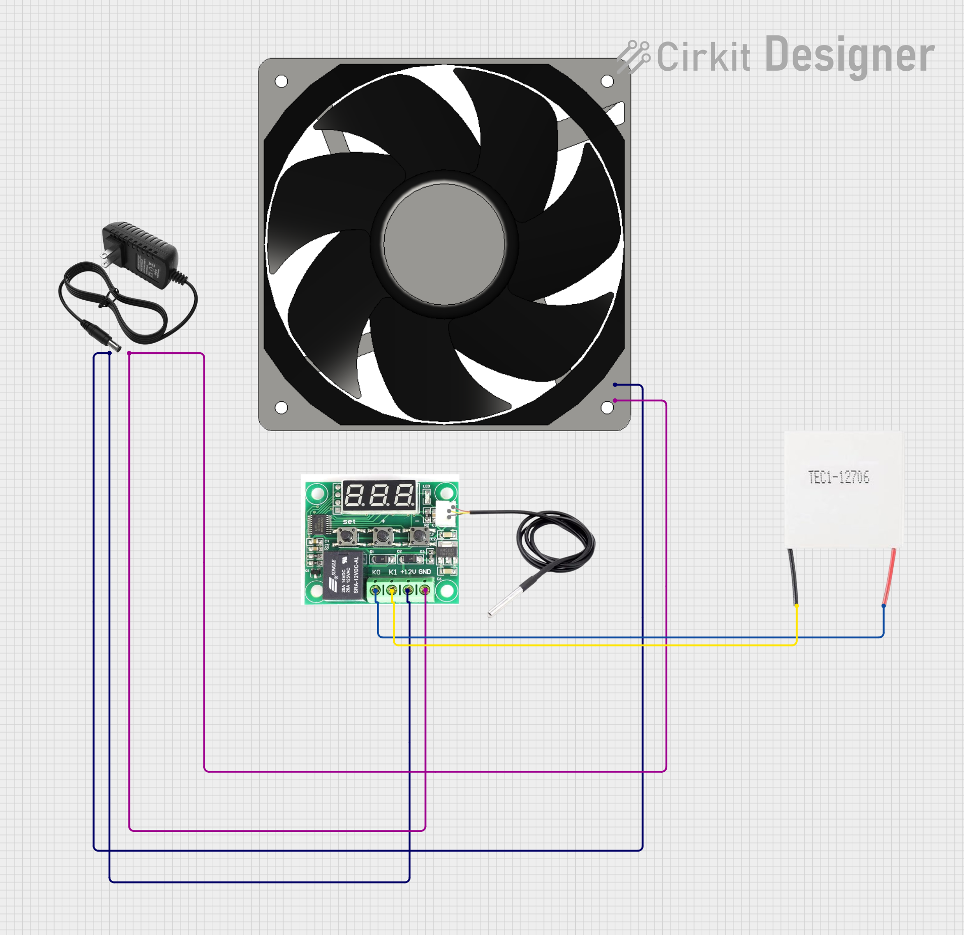

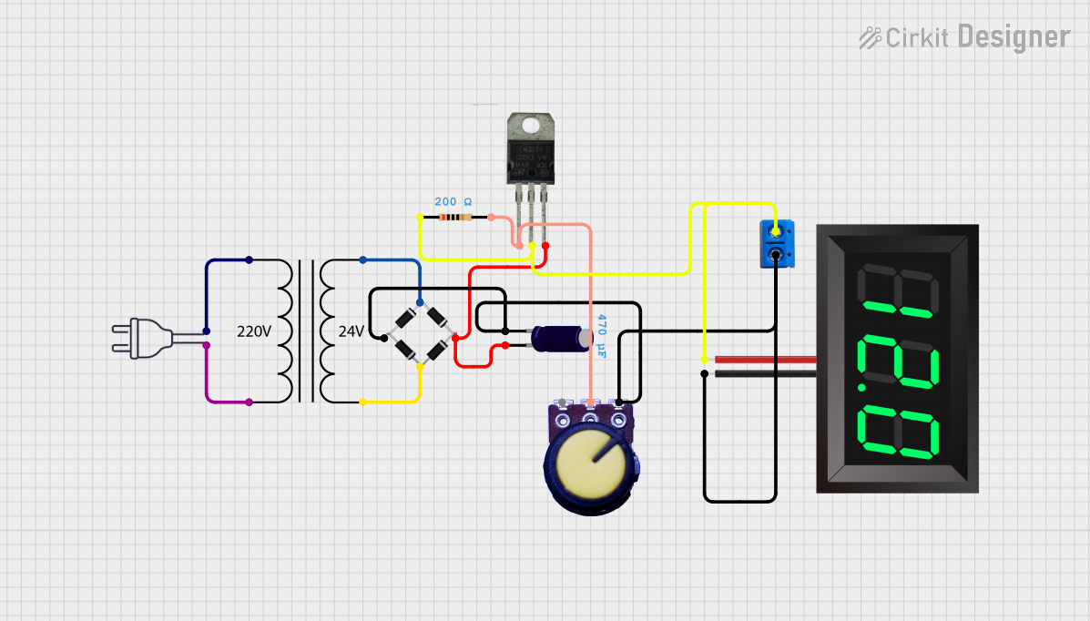
Explore Projects Built with Heatbed 220x220 24V
Common Applications and Use Cases
- 3D Printing: Ensures the first layer adheres properly to the print bed, reducing the risk of warping and improving print quality.
- Prototyping: Used in rapid prototyping to create stable and reliable prints.
- DIY Projects: Ideal for custom 3D printer builds and upgrades.
Technical Specifications
Key Technical Details
| Parameter | Value |
|---|---|
| Dimensions | 220x220 mm |
| Operating Voltage | 24V |
| Power Rating | 120W |
| Maximum Temperature | 110°C |
| Resistance | 4.8Ω |
| Connector Type | 2-pin terminal block |
Pin Configuration and Descriptions
| Pin Number | Description |
|---|---|
| 1 | Positive (+24V) |
| 2 | Negative (Ground) |
Usage Instructions
How to Use the Component in a Circuit
Wiring the Heatbed:
- Connect the positive terminal of the power supply to Pin 1 (+24V) of the heatbed.
- Connect the negative terminal of the power supply to Pin 2 (Ground) of the heatbed.
Connecting to a 3D Printer Controller:
- Most 3D printer controllers have a dedicated output for the heatbed. Ensure the controller can handle the power requirements (24V, 120W).
- Connect the heatbed terminals to the corresponding output on the controller.
Temperature Control:
- Use a thermistor or temperature sensor to monitor the heatbed temperature.
- Configure the 3D printer firmware to control the heatbed temperature based on the sensor readings.
Important Considerations and Best Practices
- Power Supply: Ensure the power supply can provide sufficient current for the heatbed (at least 5A for 24V).
- Insulation: Use an insulating material underneath the heatbed to improve heating efficiency and reduce power consumption.
- Safety: Always monitor the heatbed temperature to prevent overheating and potential damage.
- Firmware Configuration: Properly configure the 3D printer firmware to control the heatbed temperature accurately.
Troubleshooting and FAQs
Common Issues Users Might Face
Heatbed Not Heating:
- Solution: Check the power supply connections and ensure the power supply is functioning correctly. Verify that the controller is sending the correct signals to the heatbed.
Uneven Heating:
- Solution: Ensure the heatbed is properly insulated and that the thermistor is correctly positioned. Check for any damage to the heating element.
Overheating:
- Solution: Verify the firmware settings and ensure the temperature sensor is functioning correctly. Use a thermal cutoff switch as an additional safety measure.
Solutions and Tips for Troubleshooting
- Check Connections: Ensure all electrical connections are secure and free from corrosion.
- Firmware Settings: Double-check the firmware configuration for the heatbed temperature control.
- Use a Multimeter: Measure the resistance of the heatbed to ensure it matches the specified value (4.8Ω).
- Inspect for Damage: Regularly inspect the heatbed for any signs of physical damage or wear.
Example Code for Arduino UNO
If you are using an Arduino UNO to control the heatbed, you can use the following example code to manage the temperature:
// Include necessary libraries
#include <PID_v1.h>

// Define pins
const int heatbedPin = 9; // PWM pin connected to heatbed
const int tempSensorPin = A0; // Analog pin connected to thermistor

// PID control variables
double setpoint = 60.0; // Desired temperature in Celsius
double input, output;
double Kp = 2.0, Ki = 5.0, Kd = 1.0; // PID constants

// Initialize PID controller
PID myPID(&input, &output, &setpoint, Kp, Ki, Kd, DIRECT);

void setup() {
  pinMode(heatbedPin, OUTPUT);
  myPID.SetMode(AUTOMATIC);
}

void loop() {
  // Read temperature from thermistor
  int sensorValue = analogRead(tempSensorPin);
  input = map(sensorValue, 0, 1023, 0, 100); // Convert to temperature

  // Compute PID output
  myPID.Compute();

  // Control heatbed
  analogWrite(heatbedPin, output);

  // Add a delay for stability
  delay(1000);
}
This code uses a PID controller to maintain the desired temperature of the heatbed. Adjust the setpoint variable to change the target temperature. Ensure the thermistor is correctly calibrated for accurate temperature readings.
By following this documentation, users can effectively integrate and utilize the Heatbed 220x220 24V in their 3D printing setups, ensuring reliable and high-quality prints.