How to Use Alarm Bell: Examples, Pinouts, and Specs
Introduction
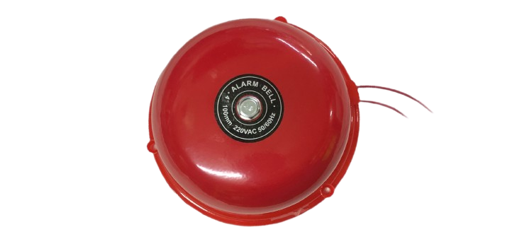
The Alarm Bell by Cin (Part ID: Cin) is a signaling device designed to produce a loud, attention-grabbing sound to alert individuals of specific events. These events may include emergencies such as fires, intrusions, or other critical situations. The alarm bell is a vital component in security systems, fire alarm systems, and industrial warning setups. Its robust design ensures reliable operation in various environments.
Explore Projects Built with Alarm Bell

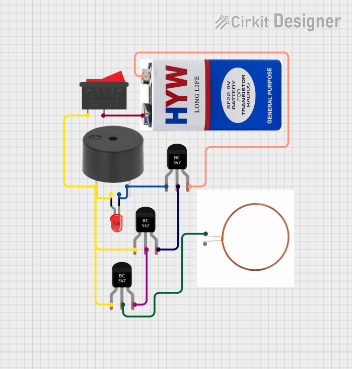
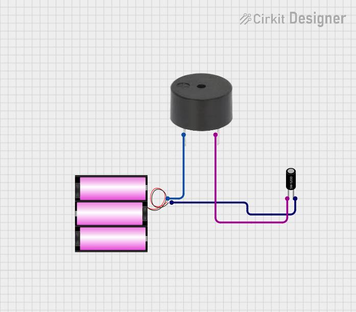
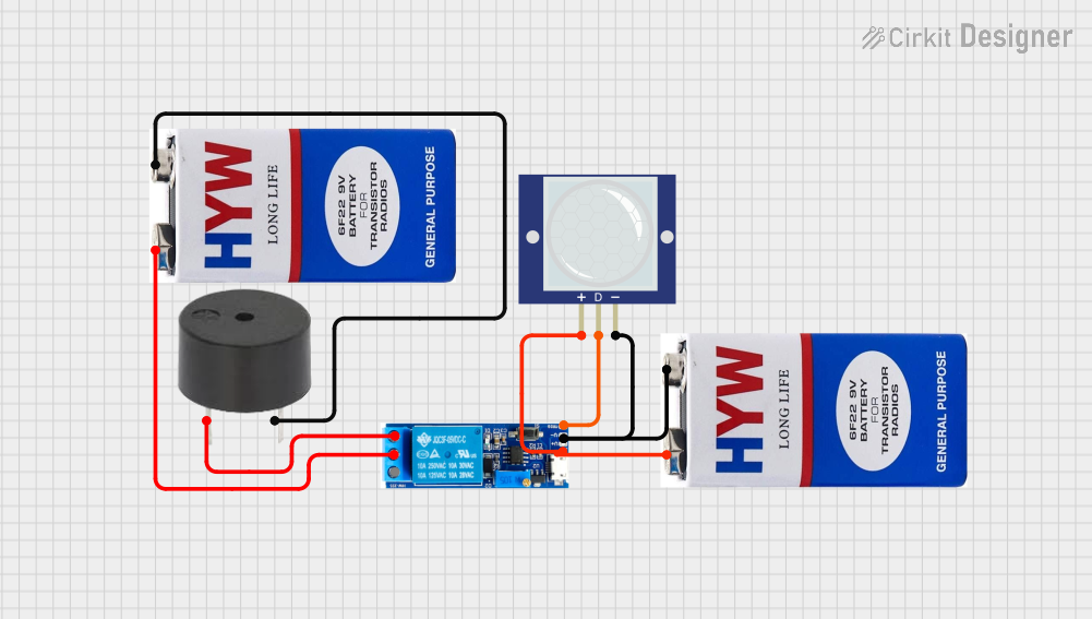
Explore Projects Built with Alarm Bell
Common Applications and Use Cases
- Fire alarm systems in residential, commercial, and industrial buildings
- Security systems for intrusion detection
- Emergency alert systems in factories and warehouses
- School and public building bell systems
- Industrial machinery status alerts
Technical Specifications
The following table outlines the key technical details of the Cin Alarm Bell:
| Parameter | Specification |
|---|---|
| Operating Voltage | 12V DC or 24V DC (model-dependent) |
| Current Consumption | 100 mA (typical) |
| Sound Output Level | 90-110 dB at 1 meter |
| Operating Temperature | -10°C to 50°C |
| Material | Metal housing with corrosion resistance |
| Mounting Type | Wall-mounted or surface-mounted |
| Dimensions | 150 mm diameter x 50 mm depth |
| Weight | 500 grams |
Pin Configuration and Descriptions
The Cin Alarm Bell typically has two connection terminals for power input. The table below describes the pin configuration:
| Pin | Label | Description |
|---|---|---|
| 1 | V+ | Positive terminal for power input (12V/24V DC) |
| 2 | GND | Ground terminal for power input |
Usage Instructions
How to Use the Alarm Bell in a Circuit
- Power Supply: Ensure the alarm bell is connected to a compatible DC power supply (12V or 24V, depending on the model). Verify the voltage and current ratings to avoid damage.
- Wiring:
- Connect the V+ terminal of the alarm bell to the positive terminal of the power supply.
- Connect the GND terminal of the alarm bell to the ground terminal of the power supply.
- Control Circuit: The alarm bell can be controlled using a relay, transistor, or microcontroller (e.g., Arduino UNO) to activate it when a specific condition is met.
- Mounting: Securely mount the alarm bell on a wall or surface using the provided mounting holes. Ensure it is placed in a location where the sound can propagate effectively.
Important Considerations and Best Practices
- Polarity: Always observe the correct polarity when connecting the power supply to avoid damage.
- Power Supply: Use a regulated DC power supply to ensure stable operation.
- Environmental Conditions: Avoid installing the alarm bell in areas exposed to excessive moisture, dust, or extreme temperatures beyond its operating range.
- Testing: Periodically test the alarm bell to ensure it is functioning correctly.
- Safety: When used in emergency systems, ensure the alarm bell is part of a regularly maintained and tested system.
Example: Connecting the Alarm Bell to an Arduino UNO
The following example demonstrates how to control the alarm bell using an Arduino UNO and a relay module.
Circuit Diagram
- Connect the V+ and GND terminals of the alarm bell to the relay module's output.
- Connect the relay module's input to the Arduino UNO's digital pin.
Code Example
// Example code to control an alarm bell using Arduino UNO and a relay module

const int relayPin = 7; // Define the digital pin connected to the relay module

void setup() {
  pinMode(relayPin, OUTPUT); // Set the relay pin as an output
  digitalWrite(relayPin, LOW); // Ensure the relay is off initially
}

void loop() {
  // Activate the alarm bell for 5 seconds
  digitalWrite(relayPin, HIGH); // Turn on the relay (activates the alarm bell)
  delay(5000); // Wait for 5 seconds
  digitalWrite(relayPin, LOW); // Turn off the relay (deactivates the alarm bell)
  delay(10000); // Wait for 10 seconds before repeating
}
Troubleshooting and FAQs
Common Issues and Solutions
| Issue | Possible Cause | Solution |
|---|---|---|
| Alarm bell does not sound | Incorrect wiring or loose connections | Verify wiring and ensure secure connections. |
| Low or distorted sound output | Insufficient power supply voltage/current | Check the power supply and ensure it meets the specifications. |
| Alarm bell activates unexpectedly | Electrical noise or faulty control circuit | Use proper filtering or shielding in the control circuit. |
| Overheating of the alarm bell | Prolonged operation beyond duty cycle | Operate the alarm bell within recommended duty cycles. |
FAQs
Can the alarm bell be used with an AC power supply?
- No, the Cin Alarm Bell is designed for DC power only. Using an AC supply may damage the device.
What is the maximum distance the sound can travel?
- The sound output level is 90-110 dB at 1 meter. The effective distance depends on environmental factors such as walls and ambient noise.
Can the alarm bell be used outdoors?
- The alarm bell is not fully weatherproof. If outdoor use is required, ensure it is installed in a protective enclosure.
How do I test the alarm bell?
- Connect the alarm bell to a compatible power supply and briefly apply power to verify sound output.
By following this documentation, users can effectively integrate and maintain the Cin Alarm Bell in their systems.