How to Use MDD20A CYTRON MOTOR DRIVER: Examples, Pinouts, and Specs
Introduction
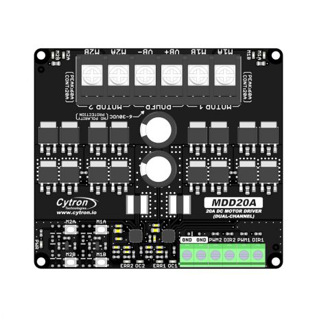
The MDD20A is a dual-channel motor driver designed for controlling DC motors and stepper motors. It is capable of handling up to 20A of continuous current per channel, making it ideal for high-power motor control applications. The driver features built-in protection mechanisms, including overcurrent and thermal overload protection, ensuring reliable operation in demanding environments. Its compact design and ease of use make it a popular choice for robotics, automation, and other motor control projects.
Explore Projects Built with MDD20A CYTRON MOTOR DRIVER


Explore Projects Built with MDD20A CYTRON MOTOR DRIVER
Common Applications
- Robotics (e.g., controlling robot wheels or arms)
- Automation systems
- Electric vehicles and carts
- Conveyor belts
- Stepper motor control for CNC machines or 3D printers
Technical Specifications
Key Technical Details
- Operating Voltage: 7V to 30V DC
- Continuous Current: 20A per channel
- Peak Current: 30A per channel (for short durations)
- Control Signals: PWM (Pulse Width Modulation) and Direction
- PWM Frequency: Up to 20 kHz
- Logic Voltage: 3.3V or 5V compatible
- Built-in Protections: Overcurrent, thermal shutdown, and undervoltage lockout
- Dimensions: 84mm x 62mm x 25mm
- Weight: Approximately 100g
Pin Configuration and Descriptions
The MDD20A has two sets of input and output terminals for controlling two motors. Below is the pin configuration:
Input Pins
| Pin Name | Description |
|---|---|
| VIN | Power supply input (7V to 30V DC). |
| GND | Ground connection for the power supply. |
| AIN1 | Input signal for Motor A direction control. |
| AIN2 | Input signal for Motor A direction control (used with AIN1). |
| PWMA | PWM input for Motor A speed control. |
| BIN1 | Input signal for Motor B direction control. |
| BIN2 | Input signal for Motor B direction control (used with BIN1). |
| PWMB | PWM input for Motor B speed control. |
| VCC | Logic voltage input (3.3V or 5V). |
Output Pins
| Pin Name | Description |
|---|---|
| Motor A+ | Positive terminal for Motor A. |
| Motor A- | Negative terminal for Motor A. |
| Motor B+ | Positive terminal for Motor B. |
| Motor B- | Negative terminal for Motor B. |
Usage Instructions
How to Use the MDD20A in a Circuit
- Power Supply: Connect a DC power supply (7V to 30V) to the VIN and GND pins. Ensure the power supply can provide sufficient current for your motors.
- Motor Connections: Connect the terminals of Motor A to Motor A+ and Motor A-, and Motor B to Motor B+ and Motor B-.
- Logic Voltage: Provide a 3.3V or 5V logic voltage to the VCC pin. This voltage should match the logic level of your microcontroller.
- Control Signals:
- Use AIN1 and AIN2 to control the direction of Motor A, and BIN1 and BIN2 for Motor B.
- Use PWMA and PWMB to control the speed of Motor A and Motor B, respectively, via PWM signals.
- Enable Protections: The MDD20A automatically handles overcurrent and thermal protection. Ensure proper ventilation to avoid thermal shutdown.
Important Considerations
- Use appropriately rated wires and connectors to handle high currents.
- Ensure the power supply voltage matches the motor's operating voltage range.
- Avoid short circuits between motor terminals or power supply connections.
- Use heat sinks or fans if the driver operates near its maximum current rating for extended periods.
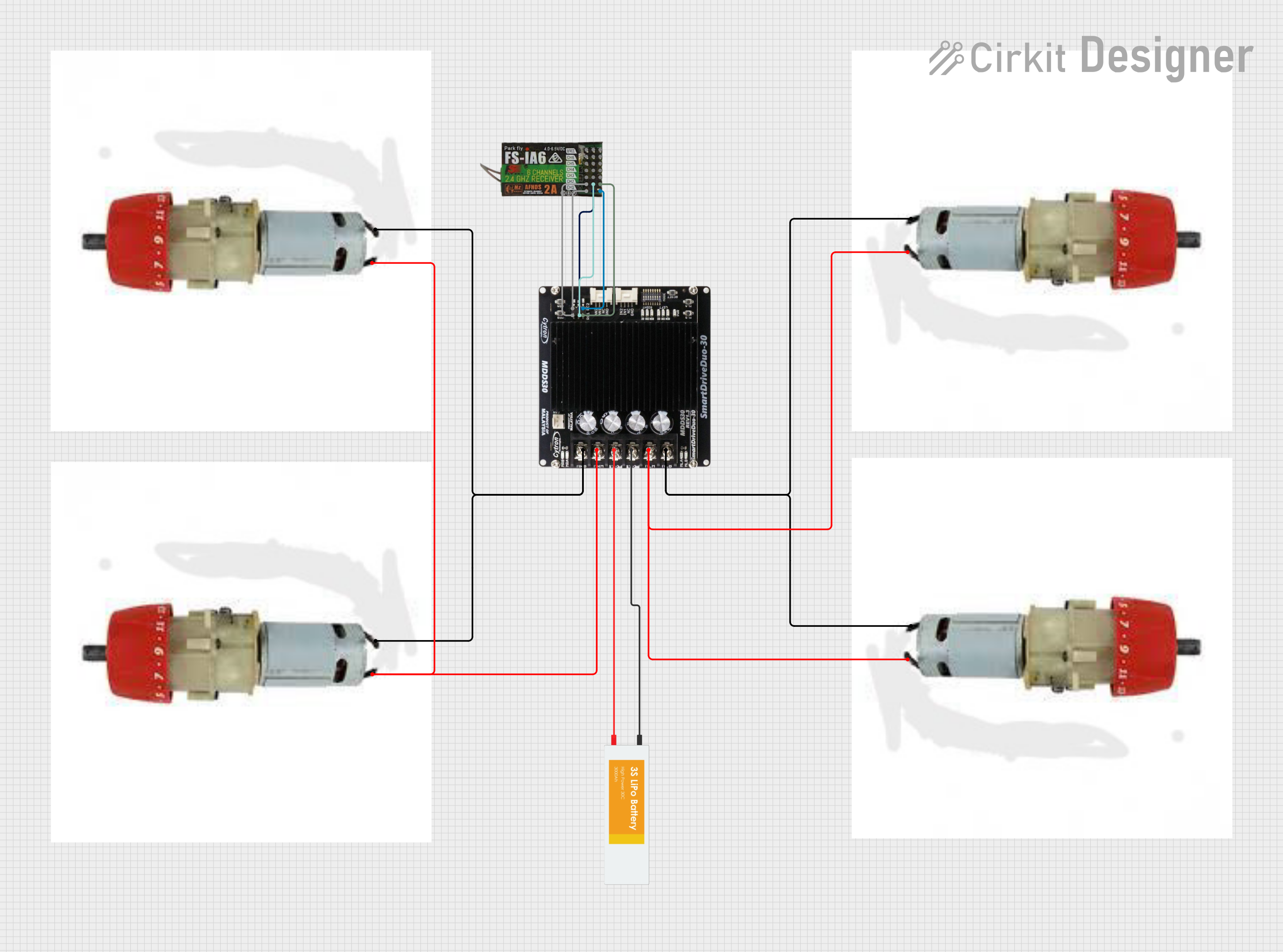
Example: Connecting to an Arduino UNO
Below is an example of how to control two DC motors using the MDD20A and an Arduino UNO.
Circuit Connections
- Connect the MDD20A's VIN and GND to a 12V power supply.
- Connect Motor A and Motor B to the respective output terminals on the MDD20A.
- Connect the Arduino's 5V pin to the MDD20A's VCC pin.
- Connect the Arduino's GND to the MDD20A's GND.
- Connect the following Arduino pins to the MDD20A:
- Pin 9 → PWMA
- Pin 8 → AIN1
- Pin 7 → AIN2
- Pin 6 → PWMB
- Pin 5 → BIN1
- Pin 4 → BIN2
Arduino Code
// Define motor control pins
#define PWMA 9  // PWM pin for Motor A
#define AIN1 8  // Direction pin 1 for Motor A
#define AIN2 7  // Direction pin 2 for Motor A
#define PWMB 6  // PWM pin for Motor B
#define BIN1 5  // Direction pin 1 for Motor B
#define BIN2 4  // Direction pin 2 for Motor B

void setup() {
  // Set motor control pins as outputs
  pinMode(PWMA, OUTPUT);
  pinMode(AIN1, OUTPUT);
  pinMode(AIN2, OUTPUT);
  pinMode(PWMB, OUTPUT);
  pinMode(BIN1, OUTPUT);
  pinMode(BIN2, OUTPUT);
}

void loop() {
  // Motor A: Forward at 50% speed
  digitalWrite(AIN1, HIGH);  // Set direction
  digitalWrite(AIN2, LOW);
  analogWrite(PWMA, 128);    // Set speed (0-255)

  // Motor B: Reverse at 75% speed
  digitalWrite(BIN1, LOW);   // Set direction
  digitalWrite(BIN2, HIGH);
  analogWrite(PWMB, 192);    // Set speed (0-255)

  delay(5000);               // Run motors for 5 seconds

  // Stop both motors
  analogWrite(PWMA, 0);
  analogWrite(PWMB, 0);

  delay(2000);               // Wait for 2 seconds
}
Troubleshooting and FAQs
Common Issues and Solutions
Motors Not Running:
- Check the power supply voltage and current rating.
- Verify all connections, especially the motor terminals and control signals.
- Ensure the logic voltage (VCC) matches the microcontroller's logic level.
Overheating:
- Ensure proper ventilation or add a heat sink/fan to the driver.
- Reduce the motor load or operating current.
Erratic Motor Behavior:
- Check for loose or poor connections.
- Verify the PWM frequency is within the supported range (up to 20 kHz).
Driver Shuts Down Unexpectedly:
- This may be due to overcurrent or thermal protection. Reduce the load or improve cooling.
FAQs
Can the MDD20A control stepper motors? Yes, the MDD20A can control stepper motors by driving the coils with appropriate signals.
What is the maximum PWM frequency supported? The MDD20A supports PWM frequencies up to 20 kHz.
Can I use a 3.3V microcontroller with the MDD20A? Yes, the MDD20A is compatible with both 3.3V and 5V logic levels.
Is it safe to operate the driver at maximum current continuously? While the MDD20A can handle 20A per channel continuously, ensure proper cooling to prevent thermal shutdown.