
How to Use GNSS receiver module: Examples, Pinouts, and Specs
 Design with GNSS receiver module in Cirkit Designer
Introduction
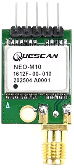
The Quescan NeoM101612F is a high-performance GNSS (Global Navigation Satellite System) receiver module designed to provide precise location data, including latitude, longitude, altitude, and time synchronization. This module is capable of receiving signals from multiple satellite constellations, such as GPS, GLONASS, Galileo, and BeiDou, ensuring reliable and accurate positioning in various environments.
Explore Projects Built with GNSS receiver module
 Open Project in Cirkit Designer
 Open Project in Cirkit Designer
 Open Project in Cirkit Designer
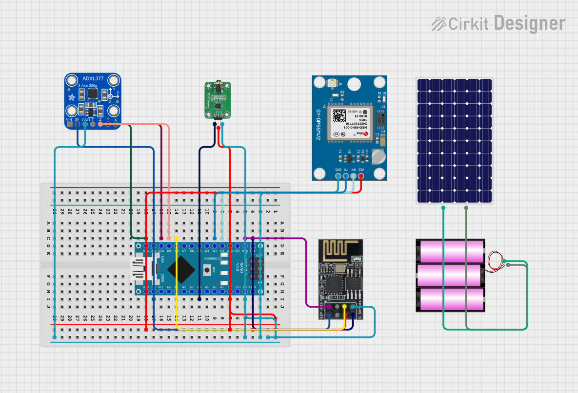 Open Project in Cirkit Designer
Explore Projects Built with GNSS receiver module
Open Project in Cirkit DesignerOpen Project in Cirkit DesignerOpen Project in Cirkit DesignerOpen Project in Cirkit DesignerCommon Applications and Use Cases
- Navigation systems for vehicles, drones, and robotics
- Geolocation in smartphones and IoT devices
- Surveying and mapping applications
- Time synchronization for telecommunications and data centers
- Asset tracking and fleet management systems
Technical Specifications
The following table outlines the key technical details of the NeoM101612F GNSS receiver module:
| Parameter | Specification |
|---|---|
| Manufacturer | Quescan |
| Part ID | NeoM101612F |
| Satellite Systems | GPS, GLONASS, Galileo, BeiDou |
| Frequency Bands | L1 (1575.42 MHz), L2 (1227.60 MHz) |
| Position Accuracy | < 2.5 meters CEP (Circular Error Probable) |
| Time to First Fix (TTFF) | Cold Start: < 30 seconds |
| Update Rate | Up to 10 Hz |
| Operating Voltage | 3.3V DC |
| Power Consumption | 40 mA (typical) |
| Communication Interface | UART, I2C |
| Operating Temperature | -40°C to +85°C |
| Dimensions | 16 mm x 12 mm x 2.5 mm |
Pin Configuration and Descriptions
The NeoM101612F module has a total of 10 pins. The pin configuration and their descriptions are provided in the table below:
| Pin Number | Pin Name | Description |
|---|---|---|
| 1 | VCC | Power supply input (3.3V DC) |
| 2 | GND | Ground connection |
| 3 | TXD | UART Transmit Data (output) |
| 4 | RXD | UART Receive Data (input) |
| 5 | SDA | I2C Data Line |
| 6 | SCL | I2C Clock Line |
| 7 | PPS | Pulse Per Second output for time synchronization |
| 8 | RESET | Active-low reset input |
| 9 | ANT_IN | External antenna input |
| 10 | NC | Not connected |
Usage Instructions
How to Use the Component in a Circuit
- Power Supply: Connect the VCC pin to a stable 3.3V DC power source and the GND pin to the ground.
- Communication Interface:
- For UART communication, connect the TXD and RXD pins to the corresponding RX and TX pins of your microcontroller.
- For I2C communication, connect the SDA and SCL pins to the respective I2C lines of your microcontroller.
- Antenna: Attach an external active antenna to the ANT_IN pin for optimal signal reception.
- Reset: Optionally, connect the RESET pin to a GPIO pin of your microcontroller for manual or software-controlled resets.
- PPS Signal: Use the PPS pin for precise time synchronization if required by your application.
Important Considerations and Best Practices
- Antenna Placement: Ensure the external antenna has a clear view of the sky for optimal satellite signal reception. Avoid placing it near metal objects or inside enclosures that block RF signals.
- Power Supply: Use a low-noise, regulated 3.3V power supply to prevent interference with the GNSS signals.
- UART/I2C Configuration: Configure the communication interface (baud rate, I2C address, etc.) according to the module's datasheet and your microcontroller's requirements.
- Cold Start vs. Hot Start: Be aware that a cold start (first-time satellite acquisition) may take longer than subsequent hot starts (reacquisition after power loss).
Example Code for Arduino UNO
Below is an example of how to interface the NeoM101612F module with an Arduino UNO using UART communication:
#include <SoftwareSerial.h>

// Define RX and TX pins for SoftwareSerial
SoftwareSerial GNSS(4, 3); // RX = Pin 4, TX = Pin 3

void setup() {
  Serial.begin(9600);       // Initialize Serial Monitor at 9600 baud
  GNSS.begin(9600);         // Initialize GNSS module at 9600 baud

  Serial.println("Initializing GNSS Receiver...");
}

void loop() {
  // Check if data is available from the GNSS module
  if (GNSS.available()) {
    // Read and print GNSS data to the Serial Monitor
    while (GNSS.available()) {
      char c = GNSS.read();
      Serial.print(c);
    }
  }
}
Note: Ensure the GNSS module's baud rate matches the value specified in GNSS.begin().
Troubleshooting and FAQs
Common Issues Users Might Face
No Satellite Fix:
- Cause: Poor antenna placement or obstructed view of the sky.
- Solution: Relocate the antenna to an open area with a clear view of the sky.
No Data Output:
- Cause: Incorrect UART or I2C connections.
- Solution: Verify the wiring and ensure the correct pins are connected.
High Power Consumption:
- Cause: Faulty power supply or excessive noise.
- Solution: Use a low-noise, regulated 3.3V power source.
Slow Time to First Fix (TTFF):
- Cause: Cold start or weak satellite signals.
- Solution: Allow the module sufficient time to acquire satellite signals, especially during the first use.
Solutions and Tips for Troubleshooting
- Use a multimeter to verify the power supply voltage at the VCC pin.
- Check the Serial Monitor for any error messages or unexpected data.
- If using I2C, ensure the pull-up resistors are correctly connected to the SDA and SCL lines.
- Consult the module's datasheet for advanced configuration options and troubleshooting steps.
By following this documentation, users can effectively integrate the Quescan NeoM101612F GNSS receiver module into their projects and achieve reliable and accurate positioning results.