Cirkit Designer Logo
Cirkit Designer
Your all-in-one circuit design IDE
Home / 
Component Documentation

How to Use Adafruit AR1100 Breakout: Examples, Pinouts, and Specs

Image of Adafruit AR1100 Breakout
Cirkit Designer LogoDesign with Adafruit AR1100 Breakout in Cirkit Designer

Introduction

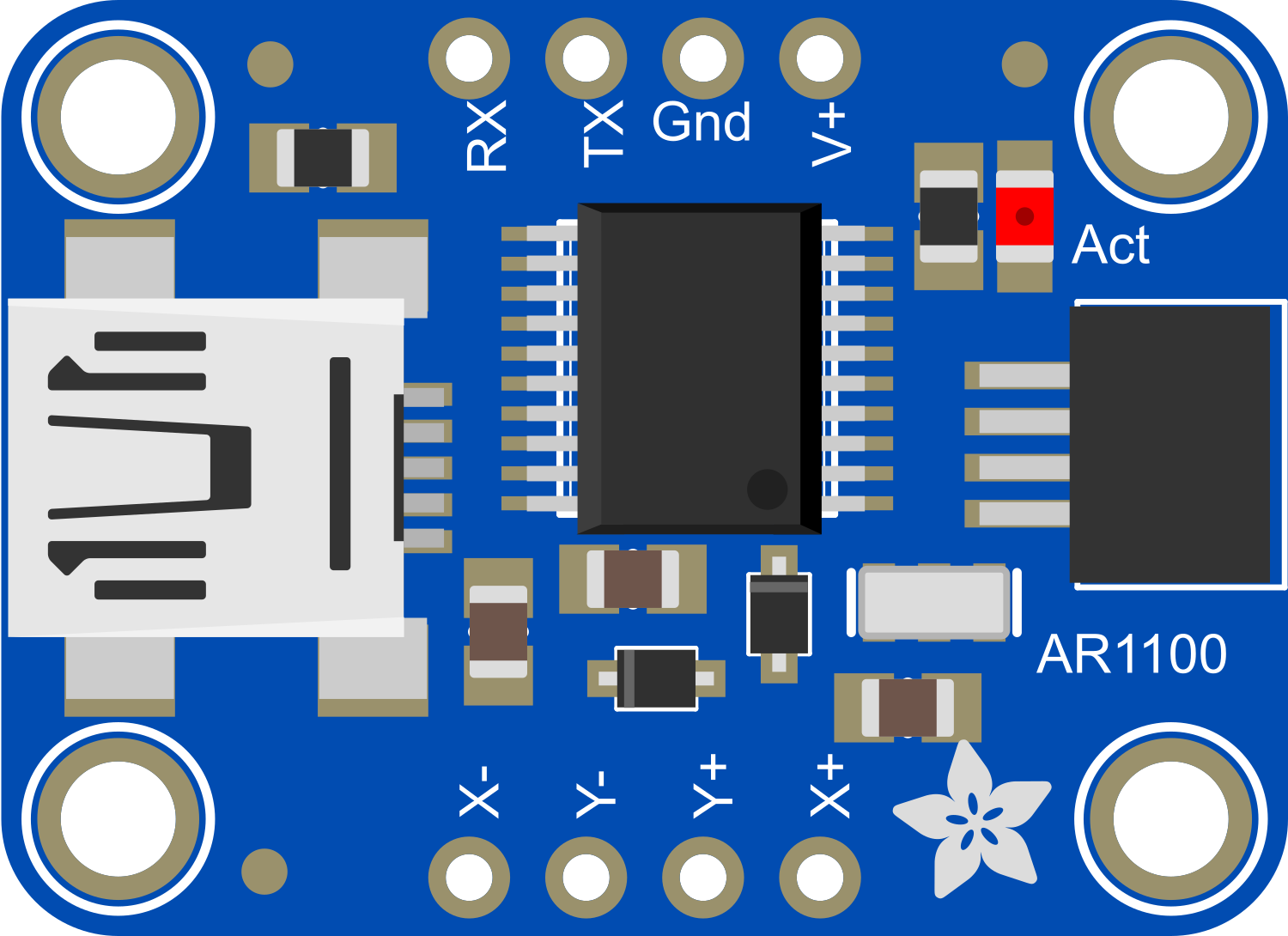
The Adafruit AR1100 Breakout is a versatile touch screen controller that enables the addition of touch input functionality to electronic projects. It operates as a USB mouse in its default state but can also be configured to communicate with microcontrollers, such as the Arduino UNO, via I2C protocol. This breakout is ideal for creating interactive projects, DIY touch panels, and integrating touch controls into various applications.

Explore Projects Built with Adafruit AR1100 Breakout

Use Cirkit Designer to design, explore, and prototype these projects online. Some projects support real-time simulation. Click "Open Project" to start designing instantly!
Arduino UNO R4 WiFi Environmental Data Logger with I2C Multiplexing and SD Storage
Image of scannerII: A project utilizing Adafruit AR1100 Breakout in a practical application
This circuit features an Arduino UNO R4 WiFi as the central microcontroller, interfaced with a BME280 Breakout sensor for environmental data, an SD card module for data logging, and a TCA9548A I2C multiplexer to manage multiple I2C devices. It also includes a U078-V-M12 sensor and an SPS30 particulate matter sensor, both connected through the I2C multiplexer. Power distribution is managed by a dedicated board that receives 3.3V from the Arduino and distributes it to the SD card module and other components.
Cirkit Designer LogoOpen Project in Cirkit Designer
Arduino UNO WiFi with Heart Pulse and Temperature Monitoring
Image of BioTrackers: A project utilizing Adafruit AR1100 Breakout in a practical application
This circuit features an Arduino UNO R4 WiFi microcontroller connected to a Heart Pulse Sensor and an SHT1x-Breakout sensor. The Arduino is configured to read heart pulse signals from the Heart Pulse Sensor on analog pin A0 and temperature/humidity data from the SHT1x-Breakout sensor via the I2C interface on pins A4 (DATA) and A5 (SCK). Both sensors are powered by the Arduino's 5V output, and their ground pins are connected to the Arduino's ground.
Cirkit Designer LogoOpen Project in Cirkit Designer
Arduino UNO-Based Bluetooth-Controlled Multi-Servo System with Ultrasonic Sensing
Image of Spider robot: A project utilizing Adafruit AR1100 Breakout in a practical application
This circuit uses an Arduino UNO to control multiple servos via an Adafruit PCA9685 PWM Servo Breakout, with power supplied by a 12V battery. It also includes an HC-05 Bluetooth module for wireless communication and an HC-SR04 ultrasonic sensor for distance measurement, with a rocker switch for manual input control.
Cirkit Designer LogoOpen Project in Cirkit Designer
Arduino Nano-Based Weather Station with Wi-Fi Connectivity and Multiple AHT10 Sensors
Image of PS2_Group 5: A project utilizing Adafruit AR1100 Breakout in a practical application
This circuit features an Arduino Nano microcontroller interfacing with three AHT10 temperature and humidity sensors, an ESP8266-01 WiFi module, and a 16x2 LCD display. It includes power regulation components to step down voltage and manage power distribution, and rocker switches for user input. The setup is designed for environmental monitoring and data display with potential for wireless communication.
Cirkit Designer LogoOpen Project in Cirkit Designer

Explore Projects Built with Adafruit AR1100 Breakout

Use Cirkit Designer to design, explore, and prototype these projects online. Some projects support real-time simulation. Click "Open Project" to start designing instantly!
Image of scannerII: A project utilizing Adafruit AR1100 Breakout in a practical application
Arduino UNO R4 WiFi Environmental Data Logger with I2C Multiplexing and SD Storage
This circuit features an Arduino UNO R4 WiFi as the central microcontroller, interfaced with a BME280 Breakout sensor for environmental data, an SD card module for data logging, and a TCA9548A I2C multiplexer to manage multiple I2C devices. It also includes a U078-V-M12 sensor and an SPS30 particulate matter sensor, both connected through the I2C multiplexer. Power distribution is managed by a dedicated board that receives 3.3V from the Arduino and distributes it to the SD card module and other components.
Cirkit Designer LogoOpen Project in Cirkit Designer
Image of BioTrackers: A project utilizing Adafruit AR1100 Breakout in a practical application
Arduino UNO WiFi with Heart Pulse and Temperature Monitoring
This circuit features an Arduino UNO R4 WiFi microcontroller connected to a Heart Pulse Sensor and an SHT1x-Breakout sensor. The Arduino is configured to read heart pulse signals from the Heart Pulse Sensor on analog pin A0 and temperature/humidity data from the SHT1x-Breakout sensor via the I2C interface on pins A4 (DATA) and A5 (SCK). Both sensors are powered by the Arduino's 5V output, and their ground pins are connected to the Arduino's ground.
Cirkit Designer LogoOpen Project in Cirkit Designer
Image of Spider robot: A project utilizing Adafruit AR1100 Breakout in a practical application
Arduino UNO-Based Bluetooth-Controlled Multi-Servo System with Ultrasonic Sensing
This circuit uses an Arduino UNO to control multiple servos via an Adafruit PCA9685 PWM Servo Breakout, with power supplied by a 12V battery. It also includes an HC-05 Bluetooth module for wireless communication and an HC-SR04 ultrasonic sensor for distance measurement, with a rocker switch for manual input control.
Cirkit Designer LogoOpen Project in Cirkit Designer
Image of PS2_Group 5: A project utilizing Adafruit AR1100 Breakout in a practical application
Arduino Nano-Based Weather Station with Wi-Fi Connectivity and Multiple AHT10 Sensors
This circuit features an Arduino Nano microcontroller interfacing with three AHT10 temperature and humidity sensors, an ESP8266-01 WiFi module, and a 16x2 LCD display. It includes power regulation components to step down voltage and manage power distribution, and rocker switches for user input. The setup is designed for environmental monitoring and data display with potential for wireless communication.
Cirkit Designer LogoOpen Project in Cirkit Designer

Technical Specifications

Key Technical Details

  • Operating Voltage: 4.0V to 5.5V
  • Current Consumption: 17 mA typical
  • Resolution: 10-bit resolution, up to 4096x4096
  • Interface: USB and I2C (selectable)
  • Touch Pressure Detection: Yes

Pin Configuration and Descriptions

Pin Number Name Description
1 VDD Power supply (4.0V to 5.5V)
2 GND Ground connection
3 SCL I2C clock line
4 SDA I2C data line
5 RST Reset pin (active low)
6 NC No connection (reserved for future use)

Usage Instructions

Integrating with a Circuit

  1. Power Supply: Connect the VDD pin to a 4.0V to 5.5V power source and the GND pin to the ground.
  2. I2C Communication: Connect the SCL and SDA pins to the corresponding I2C clock and data lines on your microcontroller.
  3. Reset Pin: The RST pin can be connected to a digital pin on your microcontroller if you wish to control the reset function programmatically.

Important Considerations and Best Practices

  • Ensure that the power supply is within the specified range to prevent damage.
  • Use pull-up resistors on the I2C lines if they are not already present on your microcontroller board.
  • When using with an Arduino, remember to connect the AR1100's SCL and SDA to the A5 and A4 pins, respectively, on an Arduino UNO.
  • For USB mode, no microcontroller is needed; the device can be connected directly to a computer.

Example Code for Arduino UNO

#include <Wire.h>

// AR1100 I2C address (may need to be adjusted based on your device)
#define AR1100_I2C_ADDRESS 0x4D

void setup() {
  Wire.begin(); // Initialize I2C
  Serial.begin(9600); // Start serial communication for debugging
}

void loop() {
  // Code to communicate with AR1100
  // This is a placeholder for actual interaction code
  // Typically, you would read touch coordinates and process them
  Serial.println("Touch screen controller active...");
  delay(1000); // Wait for a second
}

Troubleshooting and FAQs

Common Issues

  • Touch Not Responsive: Ensure that the touch screen is correctly connected to the AR1100 and that the power supply is within the specified range.
  • I2C Communication Failure: Check the wiring of the SCL and SDA pins, and ensure that pull-up resistors are in place if needed.

Solutions and Tips

  • Resetting the Device: If the device is not responding, try toggling the RST pin to reset the AR1100.
  • Updating Firmware: Ensure that the AR1100 is running the latest firmware for optimal performance.

FAQs

Q: Can the AR1100 be used with capacitive touch screens? A: Yes, the AR1100 is designed to work with resistive touch screens, but it can be configured for capacitive touch with additional components and setup.

Q: How do I change the communication mode from USB to I2C? A: The AR1100 can be configured using the AR1100 configuration utility provided by Microchip.

Q: What should I do if the touch coordinates are not accurate? A: Calibration may be necessary. Use the calibration software provided by Microchip to calibrate the touch screen.

Remember, this documentation is a starting point for working with the Adafruit AR1100 Breakout. For more detailed information, refer to the datasheet and the manufacturer's resources.