
How to Use pressure sensor: Examples, Pinouts, and Specs
 Design with pressure sensor in Cirkit Designer
Introduction
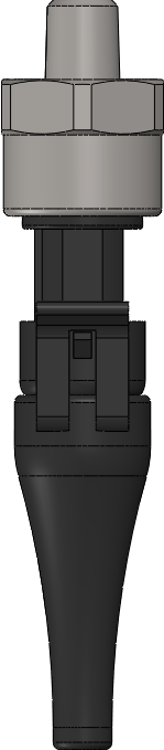
A pressure sensor is a device that measures the pressure of gases or liquids and converts it into an electrical signal for monitoring and control applications. These sensors are widely used in various industries, including automotive, medical, aerospace, and industrial automation. They play a critical role in systems that require precise pressure monitoring, such as HVAC systems, fluid dynamics studies, and weather monitoring equipment.
Common applications of pressure sensors include:
- Monitoring tire pressure in vehicles
- Measuring blood pressure in medical devices
- Detecting altitude in drones and aircraft
- Controlling industrial processes involving gases or liquids
Explore Projects Built with pressure sensor
 Open Project in Cirkit Designer
 Open Project in Cirkit Designer
 Open Project in Cirkit Designer
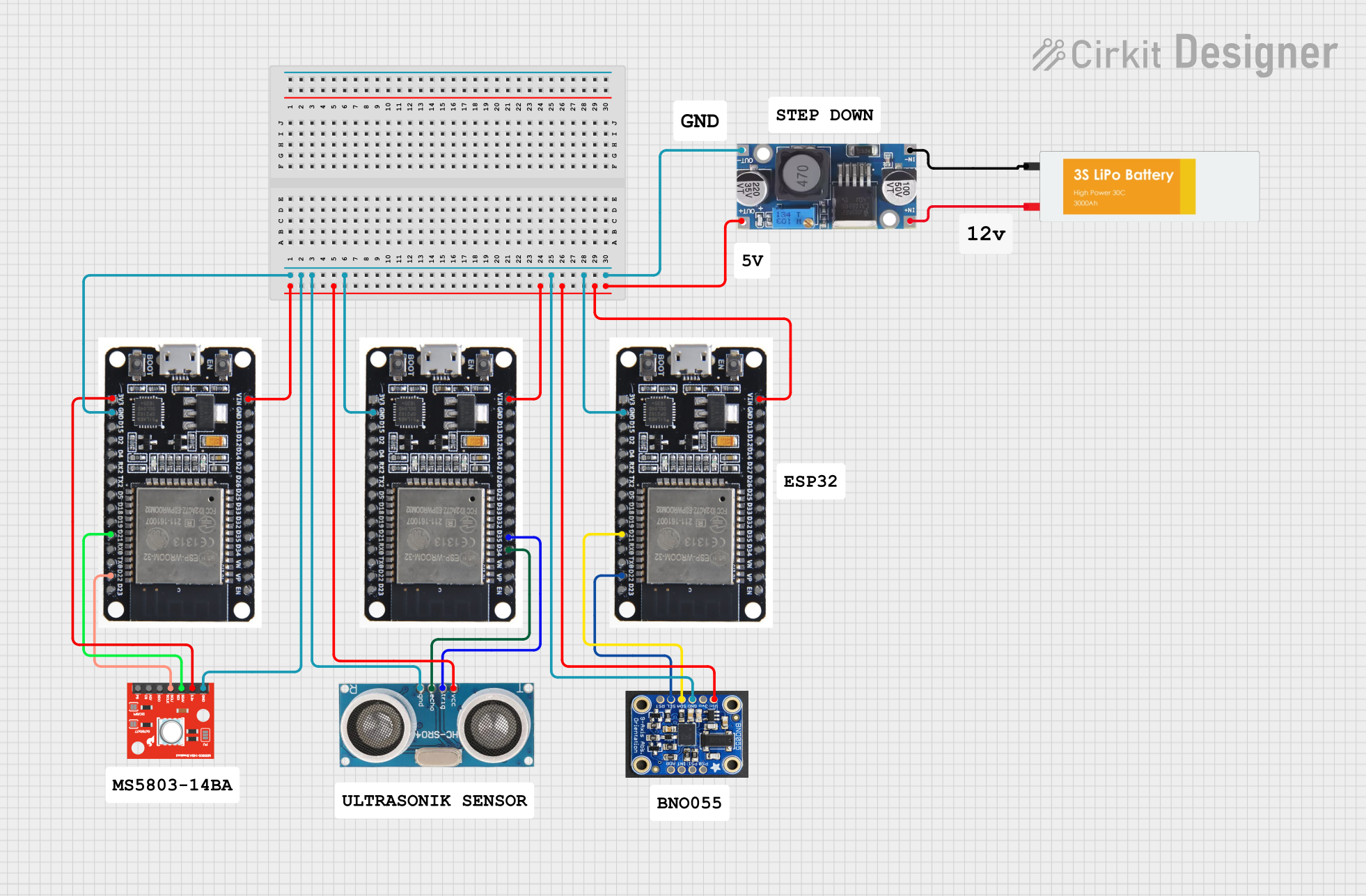 Open Project in Cirkit Designer
Explore Projects Built with pressure sensor
Open Project in Cirkit DesignerOpen Project in Cirkit DesignerOpen Project in Cirkit DesignerOpen Project in Cirkit DesignerTechnical Specifications
Below are the general technical specifications for a typical pressure sensor. Note that specific models may vary, so always refer to the datasheet of the exact sensor you are using.
Key Specifications
| Parameter | Value |
|---|---|
| Pressure Range | 0 to 100 psi (varies by model) |
| Output Signal | Analog (e.g., 0.5V to 4.5V) or Digital (I2C/SPI) |
| Supply Voltage | 3.3V or 5V |
| Operating Temperature | -40°C to +85°C |
| Accuracy | ±1% of full scale |
| Response Time | <1 ms |
Pin Configuration (Example: Analog Pressure Sensor)
| Pin Number | Pin Name | Description |
|---|---|---|
| 1 | VCC | Power supply input (3.3V or 5V) |
| 2 | GND | Ground |
| 3 | OUT | Analog output signal proportional to pressure |
Pin Configuration (Example: Digital Pressure Sensor with I2C)
| Pin Number | Pin Name | Description |
|---|---|---|
| 1 | VCC | Power supply input (3.3V or 5V) |
| 2 | GND | Ground |
| 3 | SDA | I2C data line |
| 4 | SCL | I2C clock line |
Usage Instructions
How to Use the Component in a Circuit
- Power the Sensor: Connect the
VCCpin to a 3.3V or 5V power source, depending on the sensor's specifications. Connect theGNDpin to the ground of your circuit. - Read the Output:
- For analog sensors, connect the
OUTpin to an analog input pin of your microcontroller (e.g., Arduino). - For digital sensors, connect the
SDAandSCLpins to the corresponding I2C pins on your microcontroller.
- For analog sensors, connect the
- Add a Pull-Up Resistor (if needed): For I2C communication, use pull-up resistors (typically 4.7kΩ) on the
SDAandSCLlines. - Calibrate the Sensor: Some sensors may require calibration to ensure accurate readings. Refer to the sensor's datasheet for calibration instructions.
Important Considerations and Best Practices
- Avoid Overpressure: Ensure the pressure applied to the sensor does not exceed its maximum rating to prevent damage.
- Temperature Compensation: Some sensors include built-in temperature compensation. If not, account for temperature variations in your calculations.
- Noise Filtering: Use capacitors or software filtering techniques to reduce noise in the output signal.
- Secure Mounting: Properly mount the sensor to avoid mechanical stress or vibrations that could affect accuracy.
Example Code for Arduino UNO (Analog Pressure Sensor)
// Example code to read pressure from an analog pressure sensor
// connected to an Arduino UNO. The sensor's output is connected
// to analog pin A0.

const int pressurePin = A0; // Analog pin connected to sensor output
float sensorVoltage = 0.0;  // Variable to store sensor voltage
float pressure = 0.0;       // Variable to store calculated pressure

void setup() {
  Serial.begin(9600); // Initialize serial communication
}

void loop() {
  // Read the analog value (0-1023) from the sensor
  int sensorValue = analogRead(pressurePin);

  // Convert the analog value to voltage (assuming 5V reference)
  sensorVoltage = sensorValue * (5.0 / 1023.0);

  // Convert the voltage to pressure (example: 0.5V = 0 psi, 4.5V = 100 psi)
  pressure = (sensorVoltage - 0.5) * (100.0 / (4.5 - 0.5));

  // Print the pressure value to the Serial Monitor
  Serial.print("Pressure: ");
  Serial.print(pressure);
  Serial.println(" psi");

  delay(1000); // Wait 1 second before the next reading
}
Example Code for Arduino UNO (Digital Pressure Sensor with I2C)
// Example code to read pressure from a digital pressure sensor
// using I2C communication. This example uses the Wire library.

#include <Wire.h>

const int sensorAddress = 0x28; // I2C address of the pressure sensor
float pressure = 0.0;           // Variable to store pressure value

void setup() {
  Wire.begin();          // Initialize I2C communication
  Serial.begin(9600);    // Initialize serial communication
}

void loop() {
  Wire.beginTransmission(sensorAddress); // Start communication with sensor
  Wire.requestFrom(sensorAddress, 2);   // Request 2 bytes of data

  if (Wire.available() == 2) {          // Check if 2 bytes are received
    int rawData = Wire.read() << 8 | Wire.read(); // Combine bytes
    pressure = rawData * 0.1;           // Convert raw data to pressure (example)
  }

  Serial.print("Pressure: ");
  Serial.print(pressure);
  Serial.println(" psi");

  delay(1000); // Wait 1 second before the next reading
}
Troubleshooting and FAQs
Common Issues
- No Output Signal:
- Check the power supply connections (
VCCandGND). - Verify that the sensor is receiving the correct voltage.
- Check the power supply connections (
- Inaccurate Readings:
- Ensure the sensor is calibrated correctly.
- Check for noise in the circuit and add filtering if necessary.
- I2C Communication Failure:
- Verify the I2C address of the sensor.
- Ensure pull-up resistors are connected to the
SDAandSCLlines.
FAQs
Q: Can I use a pressure sensor with a 3.3V microcontroller?
A: Yes, as long as the sensor supports a 3.3V supply. Check the datasheet for compatibility.
Q: How do I protect the sensor from overpressure?
A: Use a pressure relief valve or a mechanical stopper to prevent excessive pressure.
Q: Can I use the sensor in a high-humidity environment?
A: Some sensors are designed for harsh environments. Check the IP rating and ensure it meets your requirements.
Q: Why is my analog sensor output fluctuating?
A: This could be due to electrical noise. Add a capacitor between the OUT pin and GND to stabilize the signal.