
How to Use ASX: Examples, Pinouts, and Specs
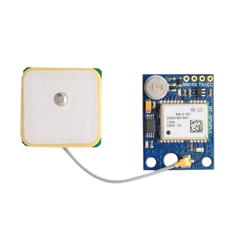
 Design with ASX in Cirkit Designer
Introduction
The ASX, manufactured by QSCXQ with the part ID SAACAS, is an analog switch designed for controlling the flow of electrical signals in electronic circuits. It operates by allowing or blocking the passage of signals based on control inputs, making it a versatile component for signal routing and switching applications. The ASX is commonly used in audio systems, data acquisition, multiplexing, and other signal processing tasks where precise control of signal paths is required.
Explore Projects Built with ASX
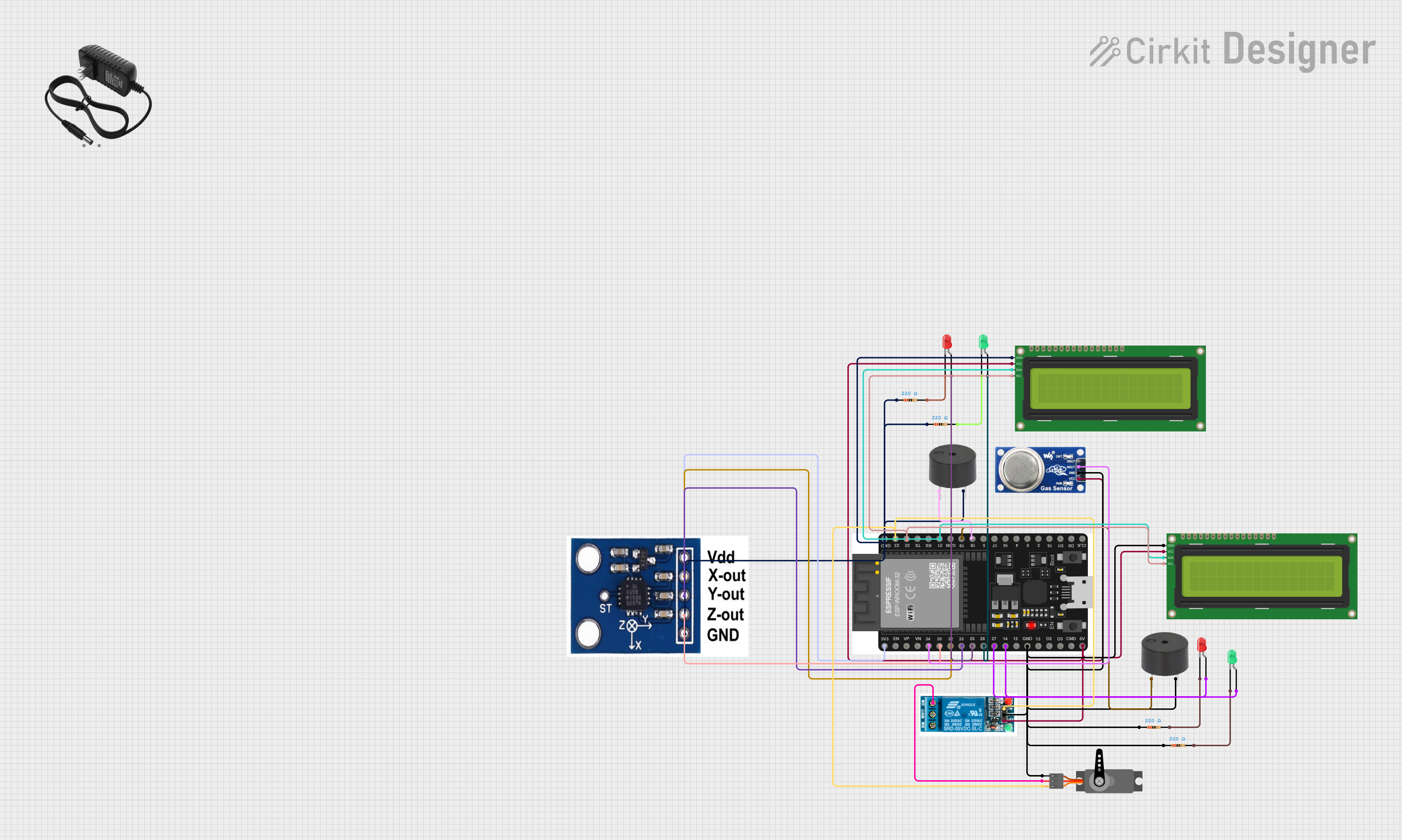
 Open Project in Cirkit Designer
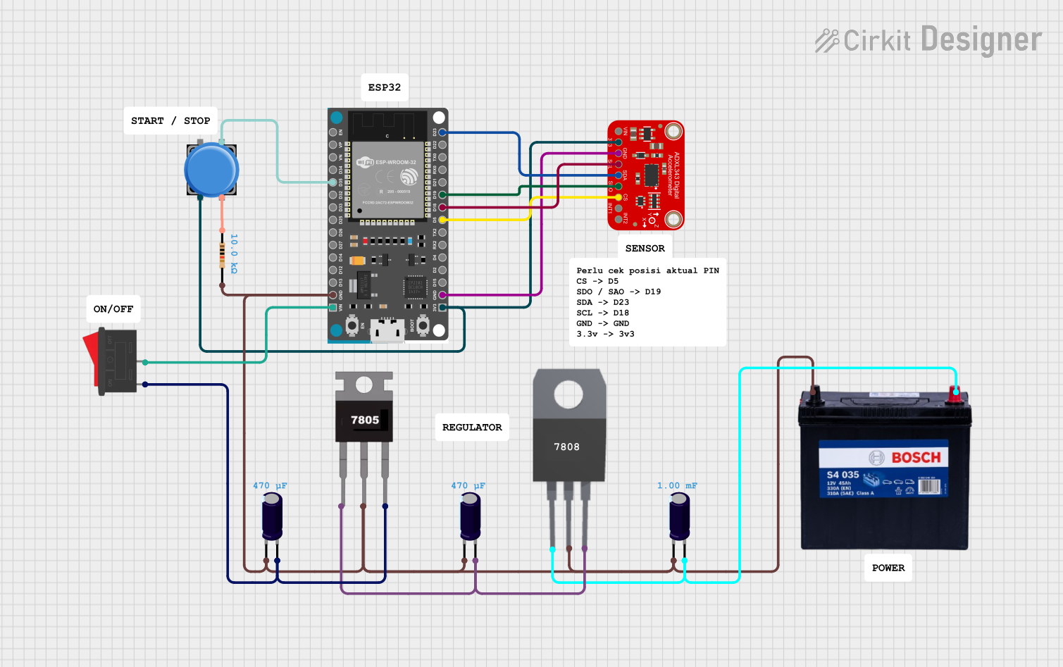
 Open Project in Cirkit Designer
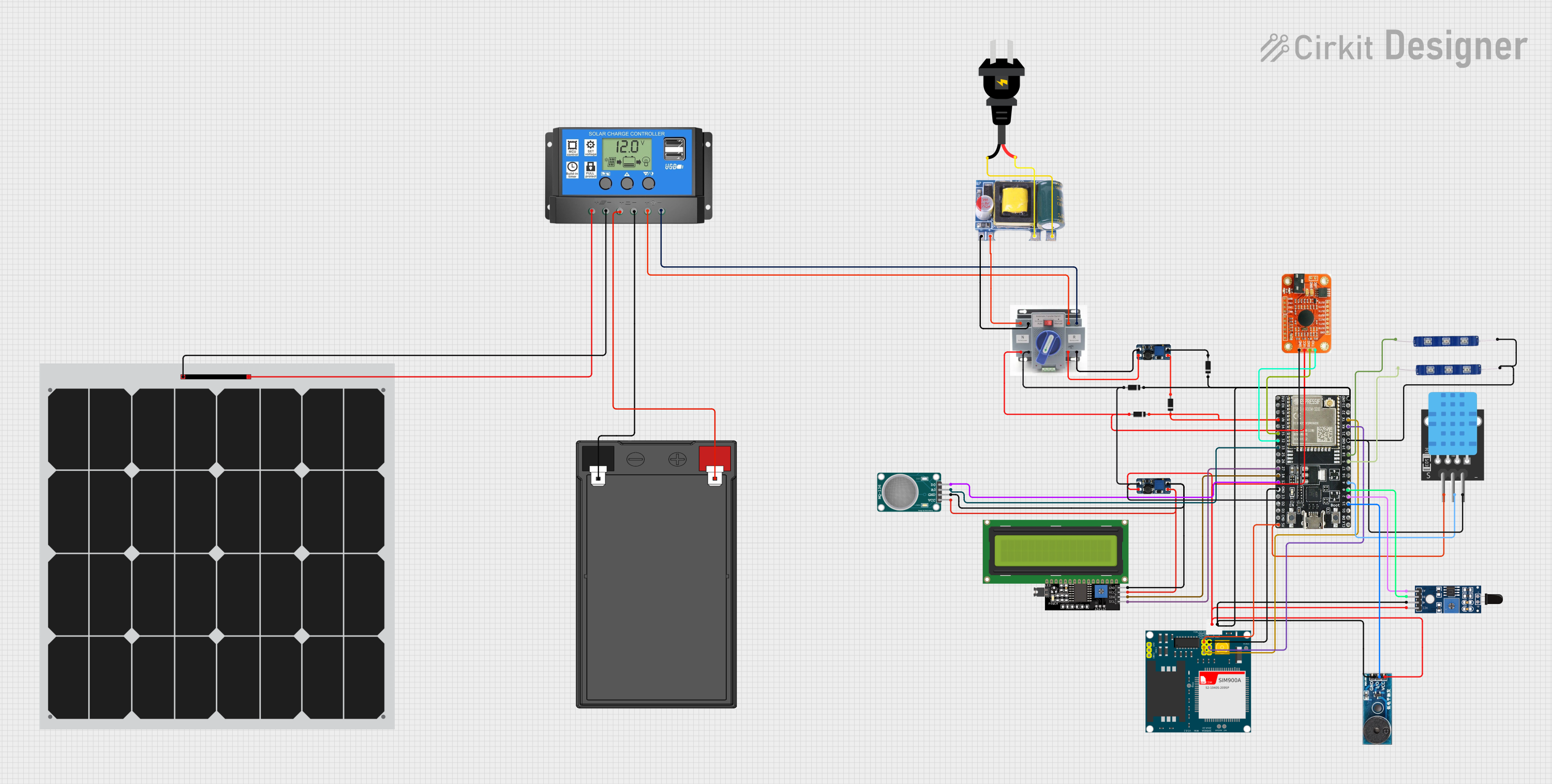
 Open Project in Cirkit Designer
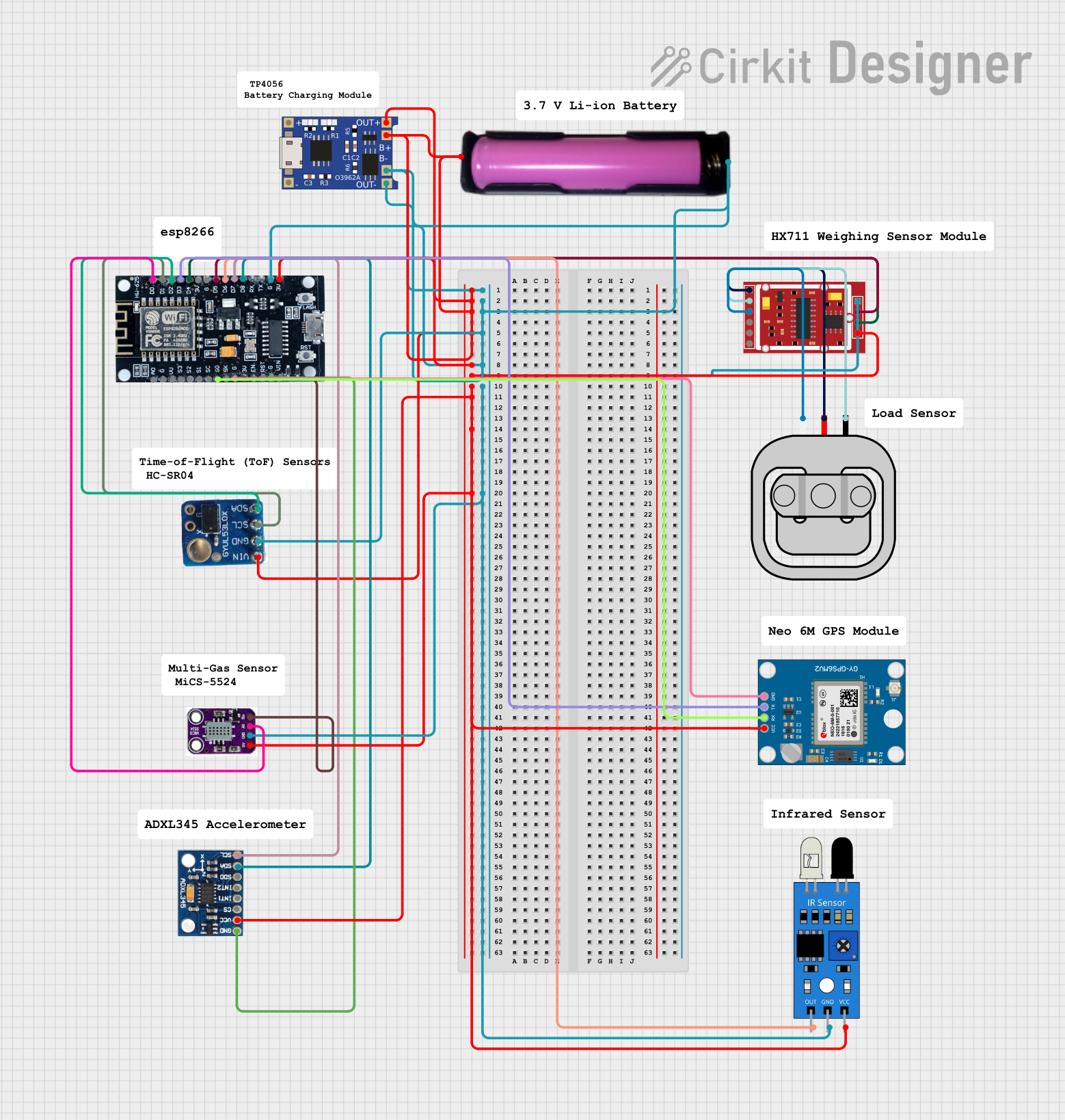
 Open Project in Cirkit Designer
Explore Projects Built with ASX

 Open Project in Cirkit Designer
 Open Project in Cirkit Designer
 Open Project in Cirkit Designer
 Open Project in Cirkit Designer
Common Applications and Use Cases
- Audio signal routing in mixers and amplifiers
- Data acquisition systems
- Multiplexing and demultiplexing signals
- Test and measurement equipment
- Low-power signal switching in portable devices
Technical Specifications
The ASX analog switch is designed to operate efficiently in a wide range of applications. Below are its key technical specifications:
| Parameter | Value |
|---|---|
| Supply Voltage (Vcc) | 2.7V to 5.5V |
| Signal Voltage Range | 0V to Vcc |
| On-Resistance (Ron) | 10Ω (typical) |
| Control Input Voltage | 0V (OFF) / Vcc (ON) |
| Bandwidth | 200 MHz |
| Power Consumption | Low power (<1 µA in standby mode) |
| Operating Temperature | -40°C to +85°C |
| Package Type | SOIC-8, TSSOP-8 |
Pin Configuration and Descriptions
The ASX is typically available in an 8-pin package. Below is the pinout and description:
| Pin Number | Pin Name | Description |
|---|---|---|
| 1 | Vcc | Positive supply voltage (2.7V to 5.5V) |
| 2 | IN | Control input for enabling/disabling the switch |
| 3 | COM | Common terminal for the switch |
| 4 | NC | Normally closed terminal of the switch |
| 5 | NO | Normally open terminal of the switch |
| 6 | GND | Ground (0V reference) |
| 7, 8 | NC | No connection (leave unconnected or grounded) |
Usage Instructions
The ASX analog switch is straightforward to use in a circuit. Below are the steps and best practices for integrating it into your design:
How to Use the ASX in a Circuit
- Power Supply: Connect the Vcc pin to a stable power supply within the range of 2.7V to 5.5V. Connect the GND pin to the circuit ground.
- Control Input: Apply a control signal to the IN pin. A logic HIGH (Vcc) enables the switch, allowing the signal to pass from the COM pin to the NO pin. A logic LOW (0V) disables the switch, blocking the signal.
- Signal Connections: Connect the input signal to the COM pin. The output signal will appear at the NO pin when the switch is enabled.
- Unused Pins: Leave the NC pin unconnected if not used, or connect it to ground to avoid floating.
Important Considerations and Best Practices
- Signal Voltage Range: Ensure the signal voltage does not exceed the supply voltage (Vcc) to prevent damage to the switch.
- On-Resistance: The ASX has a low on-resistance (10Ω typical), but consider its impact on signal integrity in high-precision applications.
- Decoupling Capacitor: Place a 0.1 µF ceramic capacitor close to the Vcc pin to filter noise and stabilize the power supply.
- Control Signal Timing: Ensure the control signal transitions are clean and within the specified voltage levels for reliable operation.
Example: Using ASX with Arduino UNO
The ASX can be controlled using a microcontroller like the Arduino UNO. Below is an example circuit and code to toggle the switch:
Circuit Connections
- Connect the Vcc pin of the ASX to the 5V pin of the Arduino.
- Connect the GND pin of the ASX to the GND pin of the Arduino.
- Connect the IN pin of the ASX to digital pin 7 of the Arduino.
- Connect the COM pin to the input signal source.
- Connect the NO pin to the output load.
Arduino Code
// Define the control pin for the ASX switch
const int controlPin = 7;

void setup() {
  // Set the control pin as an output
  pinMode(controlPin, OUTPUT);
}

void loop() {
  // Enable the switch (logic HIGH)
  digitalWrite(controlPin, HIGH);
  delay(1000); // Keep the switch ON for 1 second

  // Disable the switch (logic LOW)
  digitalWrite(controlPin, LOW);
  delay(1000); // Keep the switch OFF for 1 second
}
Troubleshooting and FAQs
Common Issues and Solutions
Switch Not Responding to Control Signal
- Cause: Incorrect voltage levels on the IN pin.
- Solution: Verify that the control signal is within the specified range (0V to Vcc).
Signal Distortion or Attenuation
- Cause: High-frequency signals may be affected by the on-resistance and parasitic capacitance.
- Solution: Use the ASX within its specified bandwidth (200 MHz) and minimize trace lengths.
Excessive Power Consumption
- Cause: Floating control input or improper grounding.
- Solution: Ensure the IN pin is either HIGH or LOW and not left floating.
Component Overheating
- Cause: Signal voltage exceeds the supply voltage or incorrect wiring.
- Solution: Verify all connections and ensure the signal voltage is within the specified range.
FAQs
Q1: Can the ASX handle AC signals?
Yes, the ASX can handle AC signals as long as the signal voltage remains within the 0V to Vcc range.
Q2: What happens if the control input is left floating?
Leaving the IN pin floating can cause unpredictable behavior. Always drive the IN pin with a defined logic level (HIGH or LOW).
Q3: Can multiple ASX switches be used in parallel?
Yes, multiple ASX switches can be used in parallel for applications like signal multiplexing. Ensure proper control signal management to avoid conflicts.
Q4: Is the ASX suitable for high-power applications?
No, the ASX is designed for low-power signal switching. For high-power applications, consider using relays or power MOSFETs.