How to Use 3S 18650 BMS: Examples, Pinouts, and Specs
Introduction
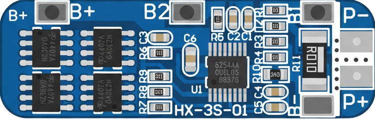
The 3S 18650 Battery Management System (BMS) is a compact and efficient module designed to manage and protect three series-connected 18650 lithium-ion cells. It ensures the safe operation of the battery pack by providing critical features such as overcharge protection, over-discharge protection, short-circuit protection, and cell balancing. These features help to extend the lifespan of the battery pack and maintain its performance.
Explore Projects Built with 3S 18650 BMS


Explore Projects Built with 3S 18650 BMS
Common Applications and Use Cases
- Power banks
- Electric bicycles and scooters
- Solar energy storage systems
- Portable electronic devices
- DIY battery packs for robotics and IoT projects
Technical Specifications
Below are the key technical details of the 3S 18650 BMS:
| Parameter | Value |
|---|---|
| Battery Configuration | 3S (Three cells in series) |
| Input Voltage Range | 9V to 12.6V |
| Overcharge Protection | 4.25V ± 0.05V per cell |
| Over-discharge Protection | 2.5V ± 0.05V per cell |
| Maximum Continuous Current | 20A |
| Balancing Current | 60mA |
| Short-circuit Protection | Yes |
| Operating Temperature Range | -40°C to 85°C |
| Dimensions | ~45mm x 15mm x 3mm |
Pin Configuration and Descriptions
The 3S 18650 BMS typically has the following pin connections:
| Pin Name | Description |
|---|---|
| B- | Battery negative terminal (connect to the negative terminal of the first cell) |
| B1 | Connection point between the first and second cells |
| B2 | Connection point between the second and third cells |
| B+ | Battery positive terminal (connect to the positive terminal of the third cell) |
| P- | Power output negative terminal (connect to the load or charger negative) |
| P+ | Power output positive terminal (connect to the load or charger positive) |
Usage Instructions
How to Use the 3S 18650 BMS in a Circuit
Connect the Batteries:
- Ensure the 18650 cells are fully discharged before connecting them to the BMS to avoid voltage mismatches.
- Connect the negative terminal of the first cell to the
B-pin. - Connect the junction between the first and second cells to the
B1pin. - Connect the junction between the second and third cells to the
B2pin. - Connect the positive terminal of the third cell to the
B+pin.
Connect the Load and Charger:
- Connect the negative terminal of the load or charger to the
P-pin. - Connect the positive terminal of the load or charger to the
P+pin.
- Connect the negative terminal of the load or charger to the
Verify Connections:
- Double-check all connections to ensure they are secure and correct.
- Use a multimeter to verify the voltage across the battery pack and ensure it matches the expected range.
Power On:
- Once all connections are verified, the BMS will automatically manage the battery pack, providing protection and balancing.
Important Considerations and Best Practices
- Cell Matching: Use 18650 cells with similar capacities, internal resistances, and charge levels to ensure proper balancing and performance.
- Heat Dissipation: Avoid enclosing the BMS in a sealed space without ventilation, as it may generate heat during operation.
- Avoid Overloading: Do not exceed the maximum continuous current rating of 20A to prevent damage to the BMS.
- Charging Voltage: Use a charger with a maximum output voltage of 12.6V to avoid overcharging the cells.
Arduino Integration Example
The 3S 18650 BMS is not directly programmable, but it can be used with an Arduino to monitor the battery pack's voltage. Below is an example code to read the voltage of the battery pack using an Arduino UNO and a voltage divider circuit:
// Arduino code to monitor the voltage of a 3S 18650 battery pack
// Ensure the voltage divider reduces the maximum 12.6V to below 5V for the Arduino

const int voltagePin = A0;  // Analog pin connected to the voltage divider
const float resistorRatio = 5.7;  // Ratio of the voltage divider resistors (e.g., 10k and 47k)
const float referenceVoltage = 5.0;  // Arduino reference voltage (5V for UNO)

void setup() {
  Serial.begin(9600);  // Initialize serial communication
}

void loop() {
  int rawValue = analogRead(voltagePin);  // Read the analog value
  float voltage = (rawValue / 1023.0) * referenceVoltage * resistorRatio;

  // Print the battery voltage to the Serial Monitor
  Serial.print("Battery Voltage: ");
  Serial.print(voltage);
  Serial.println(" V");

  delay(1000);  // Wait for 1 second before the next reading
}
Troubleshooting and FAQs
Common Issues and Solutions
BMS Not Powering On:
- Cause: Incorrect wiring or loose connections.
- Solution: Verify all connections and ensure the cells are properly connected to the BMS.
Battery Pack Not Charging:
- Cause: Charger voltage is too low or connections are incorrect.
- Solution: Use a charger with a 12.6V output and verify the
P+andP-connections.
Overheating:
- Cause: Exceeding the maximum current rating or poor ventilation.
- Solution: Reduce the load current and ensure proper heat dissipation.
Uneven Cell Voltages:
- Cause: Cells with mismatched capacities or internal resistances.
- Solution: Replace the cells with a matched set and allow the BMS to balance them over time.
FAQs
Q: Can I use the 3S 18650 BMS with fewer than three cells?
A: No, the 3S BMS is specifically designed for three series-connected cells. Using fewer cells may result in improper operation or damage.
Q: How long does it take for the BMS to balance the cells?
A: The balancing process depends on the initial voltage difference between the cells and the balancing current (60mA). It may take several hours for significant imbalances.
Q: Can I use this BMS for other lithium-ion battery types?
A: Yes, as long as the batteries have similar voltage and current characteristics to 18650 cells and are connected in a 3S configuration.