How to Use rele 220 y zocalo: Examples, Pinouts, and Specs
Introduction
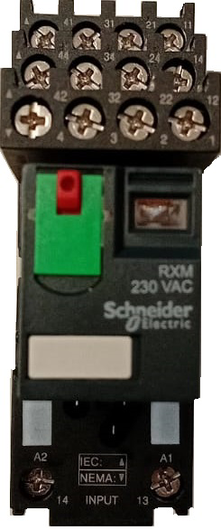
The Schneider 00001 Rele 220V with Socket is an electromechanical relay designed for switching high-voltage AC loads. It is a versatile and reliable component commonly used in industrial automation, home automation, and control systems. The relay comes with a socket for easy installation and replacement, making it ideal for applications requiring frequent maintenance or upgrades.
Explore Projects Built with rele 220 y zocalo

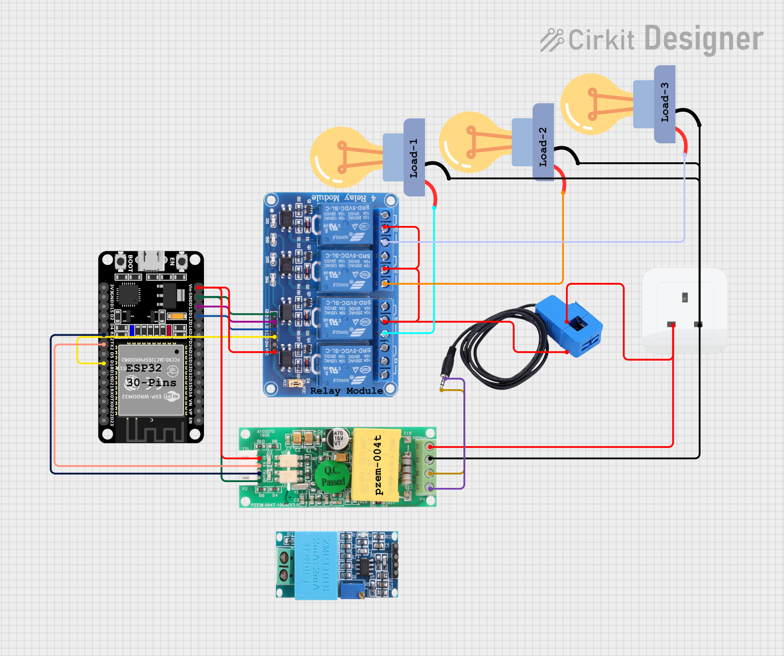
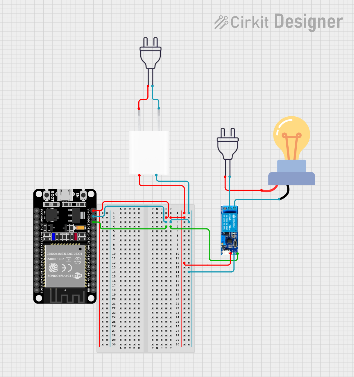

Explore Projects Built with rele 220 y zocalo
Common Applications
- Industrial machinery control
- Home automation systems (e.g., lighting, HVAC)
- Motor control circuits
- Safety and alarm systems
- Power distribution and load management
Technical Specifications
Key Technical Details
| Parameter | Value |
|---|---|
| Manufacturer | Schneider |
| Part ID | 00001 |
| Operating Voltage | 220V AC |
| Coil Voltage | 220V AC |
| Contact Configuration | SPDT (Single Pole Double Throw) |
| Contact Rating | 10A @ 250V AC |
| Insulation Resistance | ≥ 100 MΩ |
| Dielectric Strength | 2000V AC for 1 minute |
| Operating Temperature | -40°C to +70°C |
| Mounting Type | Socket (DIN rail compatible) |
Pin Configuration and Descriptions
The relay socket has a standard pin layout for easy wiring. Below is the pin configuration:
| Pin Number | Description |
|---|---|
| 1 | Coil Terminal 1 (A1) |
| 2 | Coil Terminal 2 (A2) |
| 3 | Common Contact (COM) |
| 4 | Normally Open Contact (NO) |
| 5 | Normally Closed Contact (NC) |
Usage Instructions
How to Use the Component in a Circuit
- Power the Coil: Connect the coil terminals (A1 and A2) to a 220V AC power source. Ensure proper polarity if specified.
- Connect the Load:
- For normally open operation, connect the load between the common (COM) and normally open (NO) terminals.
- For normally closed operation, connect the load between the common (COM) and normally closed (NC) terminals.
- Mounting: Secure the relay socket to a DIN rail or panel as required. Insert the relay into the socket firmly.
- Test the Circuit: Apply power to the coil and verify that the relay switches the load as expected.
Important Considerations and Best Practices
- Voltage Matching: Ensure the coil voltage matches the specified 220V AC to avoid damage.
- Contact Ratings: Do not exceed the contact rating of 10A @ 250V AC to prevent overheating or failure.
- Isolation: Maintain proper insulation and spacing between high-voltage and low-voltage sections of the circuit.
- Socket Maintenance: Periodically inspect the socket for wear or corrosion to ensure reliable connections.
- Snubber Circuit: For inductive loads (e.g., motors), use a snubber circuit or flyback diode to suppress voltage spikes.
Example: Connecting to an Arduino UNO
The relay can be controlled using an Arduino UNO with the help of a relay driver circuit (e.g., a transistor). Below is an example code snippet:
// Example: Controlling a Schneider 220V relay with Arduino UNO
// Pin 7 is used to control the relay via a transistor driver circuit.

const int relayPin = 7; // Define the pin connected to the relay driver

void setup() {
  pinMode(relayPin, OUTPUT); // Set relay pin as output
  digitalWrite(relayPin, LOW); // Ensure relay is off at startup
}

void loop() {
  digitalWrite(relayPin, HIGH); // Turn relay on
  delay(5000); // Keep relay on for 5 seconds
  digitalWrite(relayPin, LOW); // Turn relay off
  delay(5000); // Keep relay off for 5 seconds
}
Note: Use a transistor (e.g., 2N2222) and a base resistor (e.g., 1kΩ) to drive the relay coil safely from the Arduino.
Troubleshooting and FAQs
Common Issues and Solutions
Relay Not Switching:
- Cause: Insufficient coil voltage.
- Solution: Verify that the coil is receiving 220V AC. Check connections and power supply.
Contacts Not Conducting:
- Cause: Worn or damaged contacts.
- Solution: Inspect the relay contacts for wear. Replace the relay if necessary.
Excessive Heat:
- Cause: Overloaded contacts or poor ventilation.
- Solution: Ensure the load does not exceed 10A @ 250V AC. Improve ventilation around the relay.
Socket Connection Issues:
- Cause: Loose or corroded socket terminals.
- Solution: Clean the socket terminals and ensure the relay is securely seated.
FAQs
Q1: Can this relay switch DC loads?
A1: Yes, but ensure the DC load does not exceed the contact rating. For DC loads, derating may apply.
Q2: Is the relay suitable for outdoor use?
A2: The relay itself is not weatherproof. Use it in a protected enclosure for outdoor applications.
Q3: Can I use this relay with a 12V DC control signal?
A3: No, the coil is designed for 220V AC. Use a relay with a 12V DC coil or a driver circuit to interface with 12V signals.
Q4: How do I know if the relay is working?
A4: Listen for a clicking sound when the coil is energized. You can also measure continuity between the COM and NO/NC terminals.