Cirkit Designer Logo
Cirkit Designer
Your all-in-one circuit design IDE
Home / 
Component Documentation

How to Use ESP-H2-DevKitM-1: Examples, Pinouts, and Specs

Image of ESP-H2-DevKitM-1
Cirkit Designer LogoDesign with ESP-H2-DevKitM-1 in Cirkit Designer

Introduction

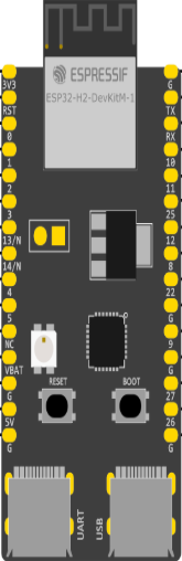
The ESP-H2-DevKitM-1, manufactured by Espressif, is a compact development kit featuring the ESP32-H2 chip. This module is designed for IoT applications, offering support for Bluetooth Low Energy (BLE) and IEEE 802.15.4 protocols. It is ideal for prototyping and integrating wireless connectivity into smart home devices, industrial automation, and other IoT projects.

Explore Projects Built with ESP-H2-DevKitM-1

Use Cirkit Designer to design, explore, and prototype these projects online. Some projects support real-time simulation. Click "Open Project" to start designing instantly!
ESP32-Based Smart Agriculture System with LoRa Communication
Image of Soil Monitoring Device: A project utilizing ESP-H2-DevKitM-1 in a practical application
This circuit features an ESP32 Devkit V1 microcontroller as the central processing unit, interfacing with various sensors including a PH Meter, an NPK Soil Sensor, and a Soil Moisture Sensor for environmental data collection. It also includes an EBYTE LoRa E220 module for wireless communication. Power management is handled by a Step Up Boost Power Converter, which is connected to a 12V Battery, stepping up the voltage to power the ESP32 and sensors, with common ground connections throughout the circuit.
Cirkit Designer LogoOpen Project in Cirkit Designer
ESP32-Based Automated Hydroponic System Controller
Image of SHy-WickS: A project utilizing ESP-H2-DevKitM-1 in a practical application
This circuit features an ESP32 Devkit V1 microcontroller connected to various sensors and devices for environmental monitoring and control. It includes a DHT11 for temperature and humidity sensing, a PH sensor, a TDS (Total Dissolved Solids) sensor, and an HC-SR04 ultrasonic sensor, likely for liquid level measurement. The ESP32 controls two 5V mini water pumps via a 2-channel relay module, and displays data on multiple I2C LCD screens.
Cirkit Designer LogoOpen Project in Cirkit Designer
ESP32-Based Environmental Monitoring and Alert System with Solar Charging
Image of mark: A project utilizing ESP-H2-DevKitM-1 in a practical application
This circuit features an ESP32 Devkit V1 microcontroller connected to various sensors and modules for monitoring and communication purposes. It includes an MQ-2 gas sensor and a DHT11 temperature and humidity sensor, both interfaced with the ESP32 for environmental data collection. The circuit is powered by a 12V battery, regulated to 5V by step-down converters, and includes a solar charge controller connected to a solar panel for battery charging, a UPS module for power management, and a SIM900A module for GSM communication. Additionally, there is a WS2812 RGB LED strip for visual feedback and a piezo buzzer for audio alerts, both controlled by the ESP32.
Cirkit Designer LogoOpen Project in Cirkit Designer
ESP32-Based Water Quality Monitoring System with I2C OLED Display and Wi-Fi Connectivity
Image of Monitoring@: A project utilizing ESP-H2-DevKitM-1 in a practical application
This circuit features an ESP32 Devkit V1 microcontroller interfaced with various sensors including a pH sensor, turbidity sensor, and TDS (Total Dissolved Solids) sensor for water quality monitoring. It also includes an OLED display for data output, a buzzer for alerts, and a two-channel relay module for controlling external devices based on sensor readings. The ESP32 facilitates data processing and I2C communication with the OLED display, while also managing sensor inputs and actuator outputs.
Cirkit Designer LogoOpen Project in Cirkit Designer

Explore Projects Built with ESP-H2-DevKitM-1

Use Cirkit Designer to design, explore, and prototype these projects online. Some projects support real-time simulation. Click "Open Project" to start designing instantly!
Image of Soil Monitoring Device: A project utilizing ESP-H2-DevKitM-1 in a practical application
ESP32-Based Smart Agriculture System with LoRa Communication
This circuit features an ESP32 Devkit V1 microcontroller as the central processing unit, interfacing with various sensors including a PH Meter, an NPK Soil Sensor, and a Soil Moisture Sensor for environmental data collection. It also includes an EBYTE LoRa E220 module for wireless communication. Power management is handled by a Step Up Boost Power Converter, which is connected to a 12V Battery, stepping up the voltage to power the ESP32 and sensors, with common ground connections throughout the circuit.
Cirkit Designer LogoOpen Project in Cirkit Designer
Image of SHy-WickS: A project utilizing ESP-H2-DevKitM-1 in a practical application
ESP32-Based Automated Hydroponic System Controller
This circuit features an ESP32 Devkit V1 microcontroller connected to various sensors and devices for environmental monitoring and control. It includes a DHT11 for temperature and humidity sensing, a PH sensor, a TDS (Total Dissolved Solids) sensor, and an HC-SR04 ultrasonic sensor, likely for liquid level measurement. The ESP32 controls two 5V mini water pumps via a 2-channel relay module, and displays data on multiple I2C LCD screens.
Cirkit Designer LogoOpen Project in Cirkit Designer
Image of mark: A project utilizing ESP-H2-DevKitM-1 in a practical application
ESP32-Based Environmental Monitoring and Alert System with Solar Charging
This circuit features an ESP32 Devkit V1 microcontroller connected to various sensors and modules for monitoring and communication purposes. It includes an MQ-2 gas sensor and a DHT11 temperature and humidity sensor, both interfaced with the ESP32 for environmental data collection. The circuit is powered by a 12V battery, regulated to 5V by step-down converters, and includes a solar charge controller connected to a solar panel for battery charging, a UPS module for power management, and a SIM900A module for GSM communication. Additionally, there is a WS2812 RGB LED strip for visual feedback and a piezo buzzer for audio alerts, both controlled by the ESP32.
Cirkit Designer LogoOpen Project in Cirkit Designer
Image of Monitoring@: A project utilizing ESP-H2-DevKitM-1 in a practical application
ESP32-Based Water Quality Monitoring System with I2C OLED Display and Wi-Fi Connectivity
This circuit features an ESP32 Devkit V1 microcontroller interfaced with various sensors including a pH sensor, turbidity sensor, and TDS (Total Dissolved Solids) sensor for water quality monitoring. It also includes an OLED display for data output, a buzzer for alerts, and a two-channel relay module for controlling external devices based on sensor readings. The ESP32 facilitates data processing and I2C communication with the OLED display, while also managing sensor inputs and actuator outputs.
Cirkit Designer LogoOpen Project in Cirkit Designer

Common Applications

  • Smart home devices (e.g., lighting, sensors, and appliances)
  • Industrial IoT (e.g., monitoring and control systems)
  • Wearable devices
  • Wireless mesh networks
  • Zigbee and Thread-based applications

Technical Specifications

Key Technical Details

Parameter Value
Chipset ESP32-H2
Wireless Protocols Bluetooth Low Energy (BLE) 5.0, IEEE 802.15.4
CPU 32-bit RISC-V single-core processor
Flash Memory 4 MB (embedded)
Operating Voltage 3.0V to 3.6V
GPIO Pins Up to 26 GPIOs
Interfaces UART, SPI, I2C, PWM, ADC
Power Consumption Ultra-low power in deep sleep mode
Dimensions 18.0 mm x 25.5 mm

Pin Configuration and Descriptions

The ESP-H2-DevKitM-1 features a 2x10 pin header layout. Below is the pinout description:

Pin Number Pin Name Functionality
1 GND Ground
2 3V3 3.3V Power Supply
3 IO0 GPIO0, used for boot mode selection
4 IO1 GPIO1, general-purpose I/O
5 IO2 GPIO2, general-purpose I/O
6 IO3 GPIO3, general-purpose I/O
7 IO4 GPIO4, general-purpose I/O
8 IO5 GPIO5, general-purpose I/O
9 RXD UART RX (Receive)
10 TXD UART TX (Transmit)
11 IO6 GPIO6, general-purpose I/O
12 IO7 GPIO7, general-purpose I/O
13 IO8 GPIO8, general-purpose I/O
14 IO9 GPIO9, general-purpose I/O
15 IO10 GPIO10, general-purpose I/O
16 IO11 GPIO11, general-purpose I/O
17 IO12 GPIO12, general-purpose I/O
18 IO13 GPIO13, general-purpose I/O
19 EN Enable pin (active high)
20 RST Reset pin

Usage Instructions

How to Use the ESP-H2-DevKitM-1 in a Circuit

  1. Power Supply: Connect the 3.3V pin to a regulated 3.3V power source and GND to ground.
  2. Programming: Use a USB-to-UART adapter to connect the RXD and TXD pins to your computer for programming. Ensure the EN pin is pulled high.
  3. Boot Mode: To enter bootloader mode, hold the IO0 pin low while resetting the module.
  4. GPIO Usage: Configure the GPIO pins as needed for your application. These pins can be used for digital I/O, PWM, ADC, or communication protocols like I2C and SPI.

Important Considerations

  • Voltage Levels: Ensure all input signals are within the 3.3V logic level to avoid damaging the module.
  • Antenna Placement: For optimal wireless performance, ensure the onboard antenna has sufficient clearance from metallic objects or other sources of interference.
  • Deep Sleep Mode: Use the deep sleep mode to minimize power consumption in battery-powered applications.

Example Code for Arduino UNO Integration

The ESP-H2-DevKitM-1 can be programmed using the Arduino IDE. Below is an example of how to blink an LED connected to GPIO2:

// Define the GPIO pin for the LED
#define LED_PIN 2

void setup() {
  // Initialize the LED pin as an output
  pinMode(LED_PIN, OUTPUT);
}

void loop() {
  // Turn the LED on
  digitalWrite(LED_PIN, HIGH);
  delay(1000); // Wait for 1 second

  // Turn the LED off
  digitalWrite(LED_PIN, LOW);
  delay(1000); // Wait for 1 second
}

Uploading Code

  1. Connect the ESP-H2-DevKitM-1 to your computer using a USB-to-UART adapter.
  2. Select the appropriate board and port in the Arduino IDE.
  3. Upload the code while ensuring the module is in bootloader mode.

Troubleshooting and FAQs

Common Issues

  1. Module Not Detected by Computer:

    • Ensure the USB-to-UART adapter is properly connected.
    • Verify that the correct COM port is selected in the Arduino IDE.
    • Check that the EN pin is pulled high.
  2. Code Upload Fails:

    • Ensure the IO0 pin is held low during reset to enter bootloader mode.
    • Verify the baud rate in the Arduino IDE matches the module's default settings.
  3. No Wireless Connectivity:

    • Check the antenna placement and ensure there are no obstructions.
    • Verify that the BLE or IEEE 802.15.4 stack is properly initialized in your code.

Tips for Troubleshooting

  • Use a multimeter to verify power supply voltages.
  • Check the serial monitor for error messages during code upload.
  • Refer to the Espressif documentation for advanced debugging techniques.

FAQs

Q: Can I use the ESP-H2-DevKitM-1 for Zigbee applications?
A: Yes, the ESP32-H2 chip supports IEEE 802.15.4, which is the foundation for Zigbee and Thread protocols.

Q: What is the maximum range of the BLE connection?
A: The BLE range depends on environmental factors but typically extends up to 100 meters in open spaces.

Q: Can I power the module using a 5V supply?
A: No, the module operates at 3.3V. Use a voltage regulator to step down 5V to 3.3V.

Q: Is the module compatible with ESP-IDF?
A: Yes, the ESP-H2-DevKitM-1 is fully supported by Espressif's ESP-IDF development framework.