How to Use GLYPHMOD-1-CH-Relay: Examples, Pinouts, and Specs
Introduction
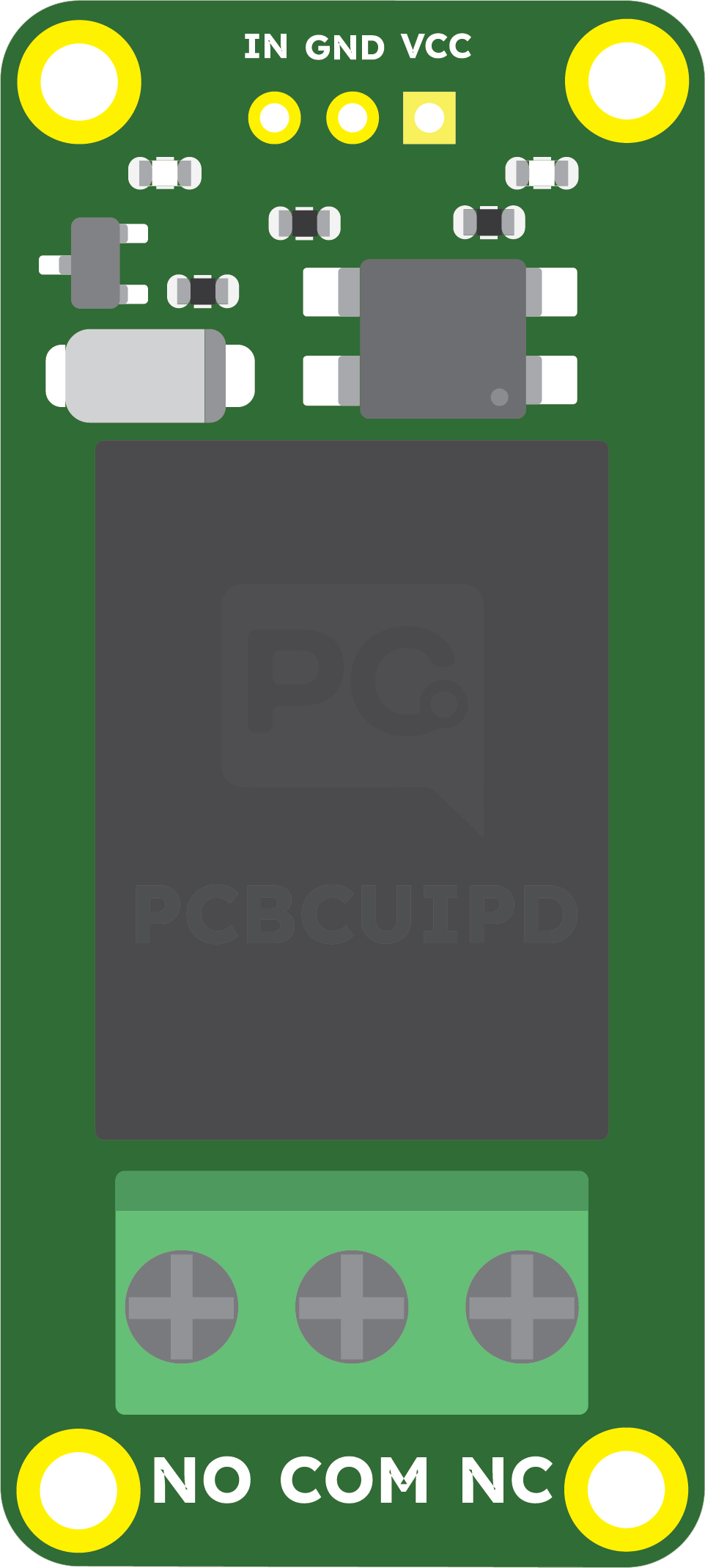
The GLYPHMOD-1-CH-Relay (Manufacturer Part ID: GM-002) is a single-channel relay module designed and manufactured by PCBCUPID. This module allows users to control high-voltage devices (e.g., appliances, lights, motors) using low-voltage control signals from microcontrollers or other logic circuits. It features opto-isolation for enhanced safety and reliability, making it ideal for applications where electrical isolation is critical.
Explore Projects Built with GLYPHMOD-1-CH-Relay
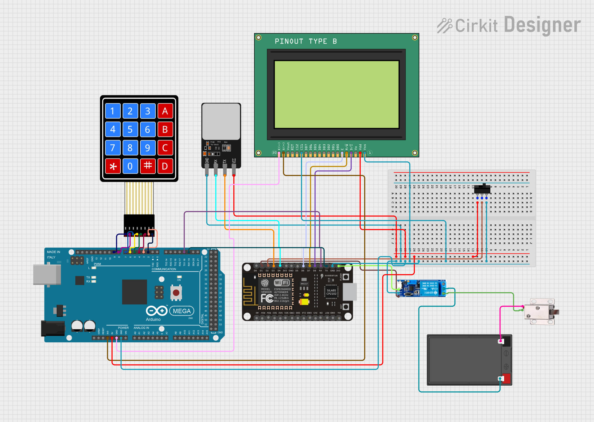

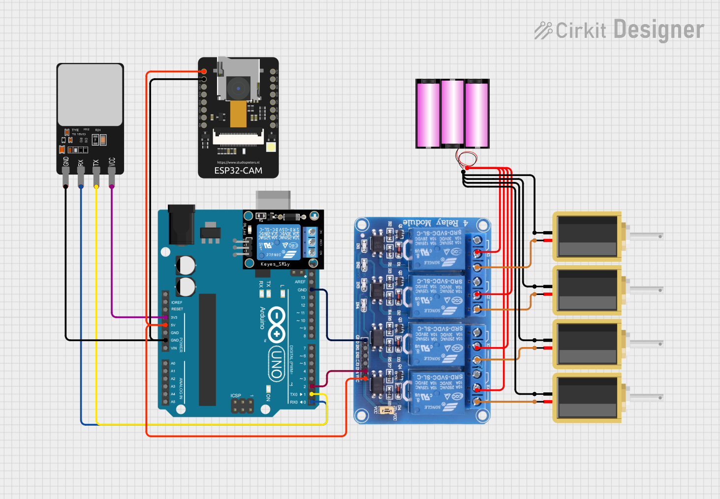
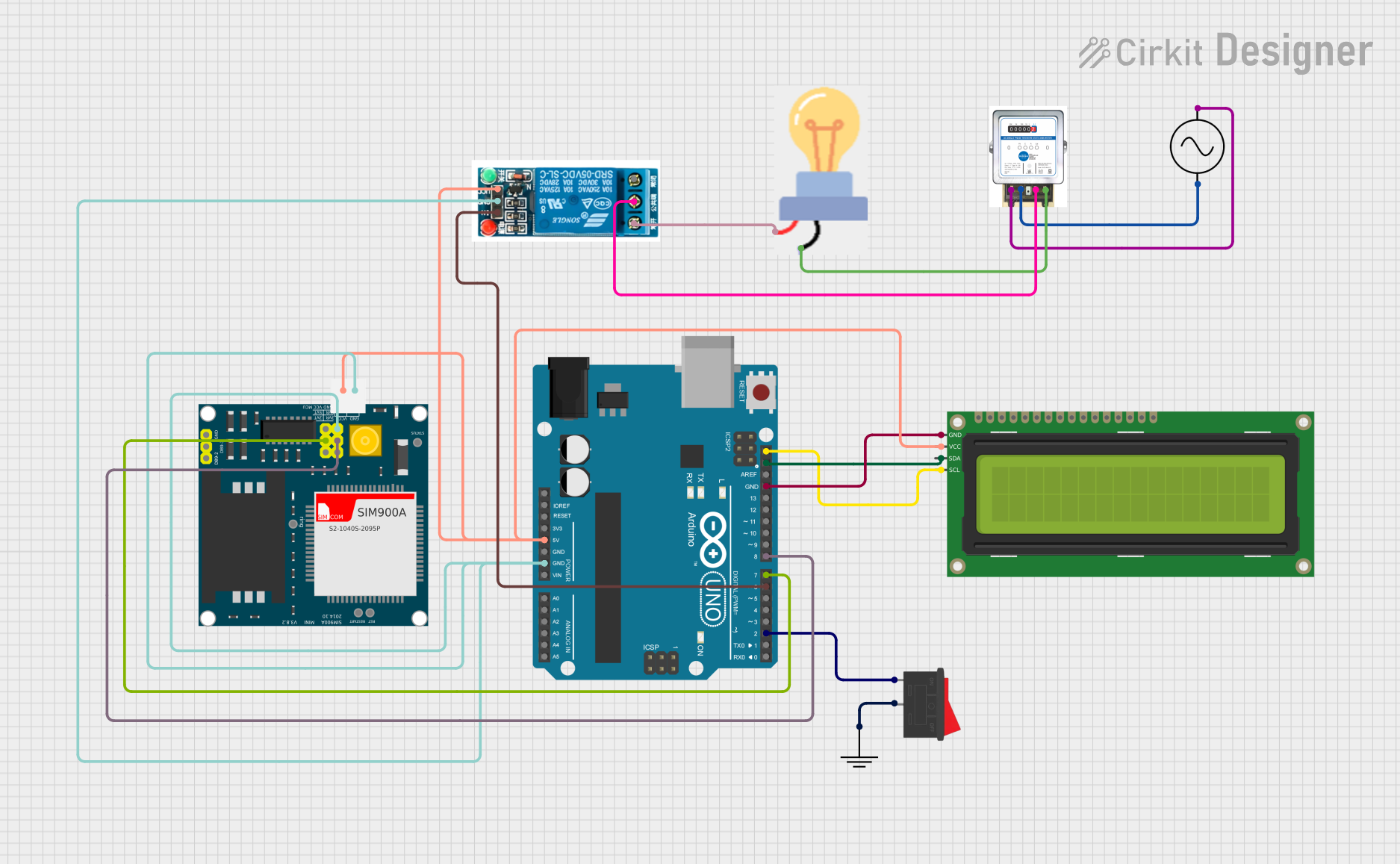
Explore Projects Built with GLYPHMOD-1-CH-Relay
Common Applications and Use Cases
- Home automation systems (e.g., controlling lights or fans)
- Industrial control systems
- IoT projects for remote device control
- Robotics and motor control
- Prototyping and educational projects
Technical Specifications
The following table outlines the key technical details of the GLYPHMOD-1-CH-Relay module:
| Parameter | Specification |
|---|---|
| Operating Voltage | 5V DC |
| Trigger Voltage | 3.3V to 5V DC |
| Relay Type | SPDT (Single Pole Double Throw) |
| Maximum Load Voltage | 250V AC / 30V DC |
| Maximum Load Current | 10A |
| Isolation Method | Opto-isolator |
| Dimensions | 50mm x 26mm x 18mm |
| Mounting | PCB mount or screw holes |
| Indicator LED | Yes (indicates relay activation) |
Pin Configuration and Descriptions
The GLYPHMOD-1-CH-Relay module has a total of 6 pins and terminals. The table below describes each pin:
Input Pins (Control Side)
| Pin Name | Description |
|---|---|
| VCC | Connect to 5V DC power supply. |
| GND | Connect to ground of the power supply. |
| IN | Control signal input (3.3V to 5V logic level). |
Output Terminals (Load Side)
| Terminal Name | Description |
|---|---|
| COM | Common terminal for the relay. |
| NO | Normally Open terminal (connected to COM when |
| the relay is activated). | |
| NC | Normally Closed terminal (connected to COM |
| when the relay is not activated). |
Usage Instructions
How to Use the GLYPHMOD-1-CH-Relay in a Circuit
- Power the Module: Connect the VCC pin to a 5V DC power supply and the GND pin to the ground of the same power supply.
- Control Signal: Connect the IN pin to a digital output pin of a microcontroller (e.g., Arduino UNO). The relay will activate when the control signal is HIGH (3.3V to 5V).
- Load Connection:
- Connect the device you want to control to the relay's output terminals (COM, NO, and NC).
- For example, connect one wire of a light bulb to the COM terminal and the other wire to the NO terminal. When the relay is activated, the circuit will close, and the light bulb will turn on.
- Indicator LED: Observe the onboard LED, which lights up when the relay is activated.
Important Considerations and Best Practices
- Isolation: Ensure proper electrical isolation between the control side (low voltage) and the load side (high voltage) to prevent damage to your microcontroller or other control circuits.
- Current Rating: Do not exceed the maximum load current of 10A to avoid damaging the relay.
- Flyback Diode: If controlling an inductive load (e.g., motor, solenoid), use a flyback diode across the load to suppress voltage spikes.
- Secure Connections: Use proper screw terminals or soldered connections for high-voltage loads to ensure safety and reliability.
Example: Using the GLYPHMOD-1-CH-Relay with an Arduino UNO
The following example demonstrates how to control the relay using an Arduino UNO:
// Example: Controlling the GLYPHMOD-1-CH-Relay with Arduino UNO

// Define the pin connected to the relay module's IN pin
const int relayPin = 7;

void setup() {
  // Set the relay pin as an output
  pinMode(relayPin, OUTPUT);

  // Ensure the relay is off at startup
  digitalWrite(relayPin, LOW);
}

void loop() {
  // Turn the relay on (activate)
  digitalWrite(relayPin, HIGH);
  delay(1000); // Keep the relay on for 1 second

  // Turn the relay off (deactivate)
  digitalWrite(relayPin, LOW);
  delay(1000); // Keep the relay off for 1 second
}
Troubleshooting and FAQs
Common Issues and Solutions
Relay Not Activating
- Cause: Insufficient control signal voltage.
- Solution: Ensure the IN pin receives a voltage between 3.3V and 5V. Check the microcontroller's output pin configuration.
Indicator LED Not Lighting Up
- Cause: No power to the module.
- Solution: Verify the VCC and GND connections. Ensure the power supply provides 5V DC.
Load Not Turning On/Off
- Cause: Incorrect wiring of the load terminals.
- Solution: Double-check the connections to the COM, NO, and NC terminals. Ensure the load is within the relay's voltage and current ratings.
Microcontroller Resetting When Relay Activates
- Cause: Voltage spikes from the load affecting the control circuit.
- Solution: Use a flyback diode across inductive loads and ensure proper grounding.
FAQs
Q1: Can I use the GLYPHMOD-1-CH-Relay with a 3.3V microcontroller?
A1: Yes, the relay module is compatible with 3.3V control signals, but ensure the VCC pin is powered with 5V DC.
Q2: Is the relay module safe for high-voltage applications?
A2: Yes, the module is designed for high-voltage applications up to 250V AC or 30V DC. However, always follow proper safety precautions when working with high voltages.
Q3: Can I control multiple relays with one microcontroller?
A3: Yes, you can control multiple relay modules by connecting each module's IN pin to a separate digital output pin on the microcontroller.
Q4: What is the purpose of the opto-isolator?
A4: The opto-isolator provides electrical isolation between the control circuit and the high-voltage load, protecting the microcontroller from voltage spikes or surges.
By following this documentation, you can safely and effectively use the GLYPHMOD-1-CH-Relay module in your projects.