How to Use AT24C256 External EEPROM: Examples, Pinouts, and Specs
Introduction
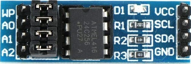
The AT24C256 External EEPROM by Hiletgo is a non-volatile memory chip that uses the I2C (Inter-Integrated Circuit) protocol for communication. With a storage capacity of 256 kilobits (32 kilobytes), it is ideal for applications that require data retention after power-off, such as storing configuration settings, calibration data, or user preferences. Common use cases include embedded systems, consumer electronics, and IoT devices.
Explore Projects Built with AT24C256 External EEPROM

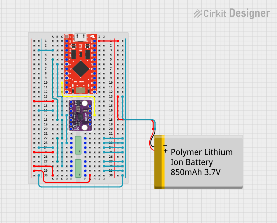

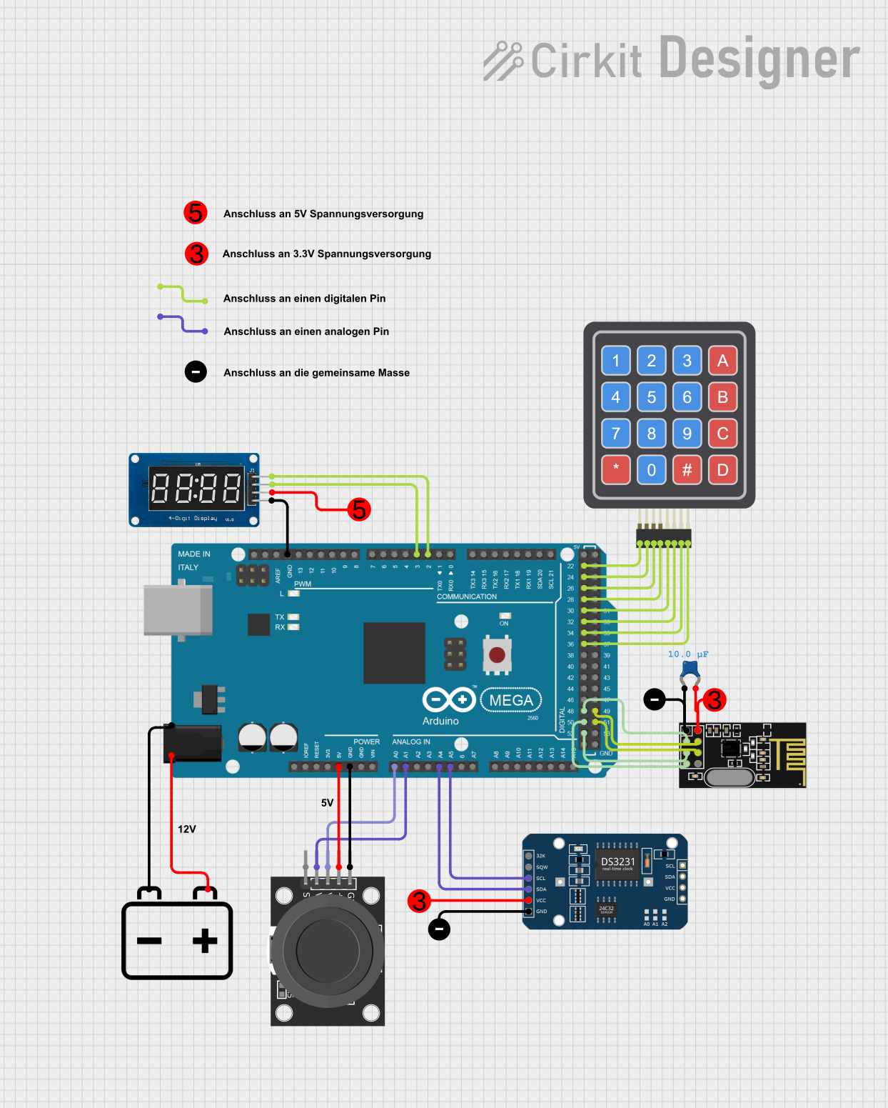
Explore Projects Built with AT24C256 External EEPROM
Technical Specifications
General Features
- Memory Size: 256 Kbit (32 Kbyte)
- Interface: I2C (Two-Wire Interface)
- Operating Voltage: 1.7V to 5.5V
- Write Cycle Time: 5 ms (max)
- Endurance: 1 Million Write Cycles
- Data Retention: 100 Years (min)
I2C Interface
- Standard Mode (100 kHz)
- Fast Mode (400 kHz)
- Fast Mode Plus (1 MHz)
Pin Configuration and Descriptions
| Pin Number | Pin Name | Description |
|---|---|---|
| 1 | A0 | Address pin 0 (configurable) |
| 2 | A1 | Address pin 1 (configurable) |
| 3 | A2 | Address pin 2 (configurable) |
| 4 | GND | Ground |
| 5 | SDA | Serial Data Line |
| 6 | SCL | Serial Clock Line |
| 7 | WP | Write Protect (active high) |
| 8 | Vcc | Supply Voltage |
Usage Instructions
Interfacing with a Circuit
- Power Supply: Connect the Vcc pin to a 1.7V to 5.5V power supply and the GND pin to the ground.
- I2C Connection: Connect the SDA and SCL pins to the I2C data and clock lines, respectively.
- Address Pins: Configure the A0, A1, and A2 pins to set the device address. These can be connected to GND or Vcc.
- Write Protection: The WP pin can be connected to Vcc to prevent writing to the EEPROM.
Best Practices
- Use pull-up resistors on the SDA and SCL lines, typically 4.7kΩ to 10kΩ.
- Ensure that the power supply is stable and within the specified voltage range.
- Avoid exposing the EEPROM to temperatures outside the specified operating range.
Example Code for Arduino UNO
#include <Wire.h>

// AT24C256 I2C address is 0x50 if all address pins (A0, A1, A2) are connected to GND
#define EEPROM_I2C_ADDRESS 0x50

void setup() {
  Wire.begin(); // Initialize I2C
  Serial.begin(9600); // Start serial communication at 9600 baud
}

void loop() {
  unsigned int address = 0; // EEPROM memory address
  byte dataToWrite = 45; // Data to write to EEPROM

  // Write data to EEPROM
  writeToEEPROM(address, dataToWrite);
  delay(10); // Short delay to ensure the write process is completed

  // Read data from EEPROM
  byte dataRead = readFromEEPROM(address);
  Serial.print("Data read from EEPROM: ");
  Serial.println(dataRead);

  delay(2000); // Wait for 2 seconds before next read/write
}

void writeToEEPROM(unsigned int address, byte data) {
  Wire.beginTransmission(EEPROM_I2C_ADDRESS);
  Wire.write((int)(address >> 8)); // MSB
  Wire.write((int)(address & 0xFF)); // LSB
  Wire.write(data);
  Wire.endTransmission();

  delay(5); // EEPROM write cycle time (max 5ms)
}

byte readFromEEPROM(unsigned int address) {
  byte data = 0xFF; // Data read from EEPROM

  Wire.beginTransmission(EEPROM_I2C_ADDRESS);
  Wire.write((int)(address >> 8)); // MSB
  Wire.write((int)(address & 0xFF)); // LSB
  Wire.endTransmission();

  Wire.requestFrom(EEPROM_I2C_ADDRESS, 1);
  if (Wire.available()) data = Wire.read();

  return data;
}
Troubleshooting and FAQs
Common Issues
- Data Not Retained: Ensure the WP pin is not active unless write protection is desired.
- Incorrect Data Read: Verify the I2C address and connections. Check pull-up resistors on SDA and SCL lines.
- No Communication: Confirm that the power supply is within the specified range and that the I2C bus is not busy or stuck.
FAQs
Q: How do I set the I2C address for the AT24C256? A: The I2C address is determined by the state of the A0, A1, and A2 pins. Connect these pins to GND or Vcc to set the address.
Q: Can I connect multiple AT24C256 devices on the same I2C bus? A: Yes, you can connect up to 8 devices by configuring the A0, A1, and A2 pins with different combinations.
Q: What is the purpose of the WP pin? A: The WP (Write Protect) pin is used to prevent accidental writes to the EEPROM. When connected to Vcc, the device is write-protected.
For further assistance, consult the manufacturer's datasheet and application notes.