How to Use ICM-20602: Examples, Pinouts, and Specs

 Design with ICM-20602 in Cirkit Designer
Introduction
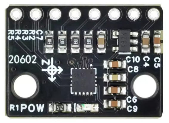
The ICM-20602 is a high-performance 6-axis motion tracking device that integrates a 3-axis gyroscope and a 3-axis accelerometer into a single compact package. This sensor is designed for applications requiring precise motion sensing and orientation detection. It is widely used in drones, smartphones, wearable devices, gaming controllers, and other systems where accurate motion tracking is essential.
The ICM-20602 offers low power consumption, high sensitivity, and a wide range of programmable features, making it suitable for both consumer and industrial applications. Its small form factor and robust design allow it to be easily integrated into space-constrained devices.
Explore Projects Built with ICM-20602

 Open Project in Cirkit Designer
 Open Project in Cirkit Designer
 Open Project in Cirkit Designer
 Open Project in Cirkit Designer
Explore Projects Built with ICM-20602

 Open Project in Cirkit Designer
 Open Project in Cirkit Designer
 Open Project in Cirkit Designer
 Open Project in Cirkit Designer
Technical Specifications
Key Specifications
| Parameter | Value |
|---|---|
| Gyroscope Range | ±250, ±500, ±1000, ±2000 dps |
| Accelerometer Range | ±2g, ±4g, ±8g, ±16g |
| Gyroscope Sensitivity | 16.4 LSB/dps (±2000 dps) |
| Accelerometer Sensitivity | 16384 LSB/g (±2g) |
| Operating Voltage | 1.71V to 3.6V |
| Communication Interface | I²C (up to 400 kHz) / SPI (up to 10 MHz) |
| Operating Temperature | -40°C to +85°C |
| Package Size | 3 mm x 3 mm x 0.75 mm |
Pin Configuration
The ICM-20602 is typically available in a 16-pin LGA package. Below is the pin configuration:
| Pin Number | Pin Name | Description |
|---|---|---|
| 1 | VDD | Power supply input (1.71V to 3.6V) |
| 2 | VDDIO | I/O voltage reference |
| 3 | GND | Ground |
| 4 | FSYNC | Frame synchronization input |
| 5 | INT | Interrupt output |
| 6 | SCL/SCLK | I²C clock / SPI clock input |
| 7 | SDA/SDI | I²C data / SPI data input |
| 8 | SDO | SPI data output |
| 9 | nCS | SPI chip select (active low) |
| 10-16 | NC | No connection (leave unconnected) |
Usage Instructions
How to Use the ICM-20602 in a Circuit
- Power Supply: Connect the VDD pin to a stable power source (1.71V to 3.6V) and the GND pin to ground. Ensure that the VDDIO pin matches the logic level of your microcontroller (e.g., 3.3V or 1.8V).
- Communication Interface: Choose between I²C or SPI for communication:
- For I²C, connect the SCL and SDA pins to the corresponding I²C pins on your microcontroller. Use pull-up resistors (typically 4.7 kΩ) on both lines.
- For SPI, connect SCLK, SDI, SDO, and nCS to the appropriate SPI pins on your microcontroller.
- Interrupts: If needed, connect the INT pin to a GPIO pin on your microcontroller to handle interrupts.
- Bypass Capacitors: Place a 0.1 µF decoupling capacitor close to the VDD pin to reduce noise.
Best Practices
- Use proper PCB layout techniques to minimize noise and interference.
- Avoid placing the sensor near high-frequency components or heat sources.
- Calibrate the sensor for your specific application to improve accuracy.
- Use the built-in digital low-pass filter (DLPF) to reduce noise in the output data.
Example Code for Arduino UNO
Below is an example of how to interface the ICM-20602 with an Arduino UNO using the I²C protocol:
#include <Wire.h>

// ICM-20602 I2C address (default is 0x68 when AD0 is low)
#define ICM20602_ADDR 0x68

// Register addresses
#define WHO_AM_I 0x75
#define PWR_MGMT_1 0x6B
#define ACCEL_XOUT_H 0x3B

void setup() {
  Wire.begin(); // Initialize I2C communication
  Serial.begin(9600); // Initialize serial communication for debugging

  // Wake up the ICM-20602
  Wire.beginTransmission(ICM20602_ADDR);
  Wire.write(PWR_MGMT_1); // Power management register
  Wire.write(0x00); // Set to 0 to wake up the sensor
  Wire.endTransmission();

  // Verify communication by reading the WHO_AM_I register
  Wire.beginTransmission(ICM20602_ADDR);
  Wire.write(WHO_AM_I);
  Wire.endTransmission();
  Wire.requestFrom(ICM20602_ADDR, 1);

  if (Wire.available()) {
    byte whoAmI = Wire.read();
    if (whoAmI == 0x12) { // Expected WHO_AM_I value for ICM-20602
      Serial.println("ICM-20602 detected!");
    } else {
      Serial.print("Unexpected WHO_AM_I value: 0x");
      Serial.println(whoAmI, HEX);
    }
  } else {
    Serial.println("Failed to communicate with ICM-20602.");
  }
}

void loop() {
  // Read accelerometer data (X-axis high byte)
  Wire.beginTransmission(ICM20602_ADDR);
  Wire.write(ACCEL_XOUT_H);
  Wire.endTransmission();
  Wire.requestFrom(ICM20602_ADDR, 1);

  if (Wire.available()) {
    int16_t accelX = Wire.read() << 8; // Read high byte
    accelX |= Wire.read(); // Read low byte
    Serial.print("Accelerometer X: ");
    Serial.println(accelX);
  }

  delay(500); // Delay for readability
}
Notes:
- Replace the
0x12value in theWHO_AM_Icheck with the correct value if your specific ICM-20602 variant differs. - Ensure pull-up resistors are connected to the I²C lines.
Troubleshooting and FAQs
Common Issues
No Communication with the Sensor:
- Ensure the I²C or SPI connections are correct.
- Verify that the sensor is powered and the VDDIO voltage matches the microcontroller's logic level.
- Check for proper pull-up resistors on the I²C lines.
Incorrect or No Data Output:
- Confirm that the sensor is properly initialized (e.g., wake-up command sent to
PWR_MGMT_1). - Verify the register addresses and data format in your code.
- Confirm that the sensor is properly initialized (e.g., wake-up command sent to
High Noise in Sensor Data:
- Enable the digital low-pass filter (DLPF) to reduce noise.
- Ensure the sensor is mounted securely to avoid mechanical vibrations.
FAQs
Q: Can the ICM-20602 operate at 5V?
A: No, the maximum operating voltage for the ICM-20602 is 3.6V. Use a voltage regulator or level shifter if interfacing with a 5V system.
Q: How do I switch between I²C and SPI modes?
A: The ICM-20602 defaults to I²C mode. To use SPI, connect the nCS pin to the microcontroller and ensure it is pulled low during communication.
Q: What is the purpose of the FSYNC pin?
A: The FSYNC pin is used for frame synchronization in applications requiring precise timing, such as multi-sensor setups.
Q: How do I calibrate the sensor?
A: Perform a calibration routine to account for offsets and biases in the accelerometer and gyroscope. This can be done in software by averaging readings when the sensor is stationary.