How to Use ESP8266 WIFI: Examples, Pinouts, and Specs
Introduction
The ESP8266 is a low-cost Wi-Fi microchip with a full TCP/IP stack and microcontroller capability. It is widely used in Internet of Things (IoT) applications to enable wireless connectivity for devices. The ESP8266 can operate as both a standalone microcontroller or as a Wi-Fi module for other microcontrollers, making it a versatile choice for a variety of projects.
Explore Projects Built with ESP8266 WIFI

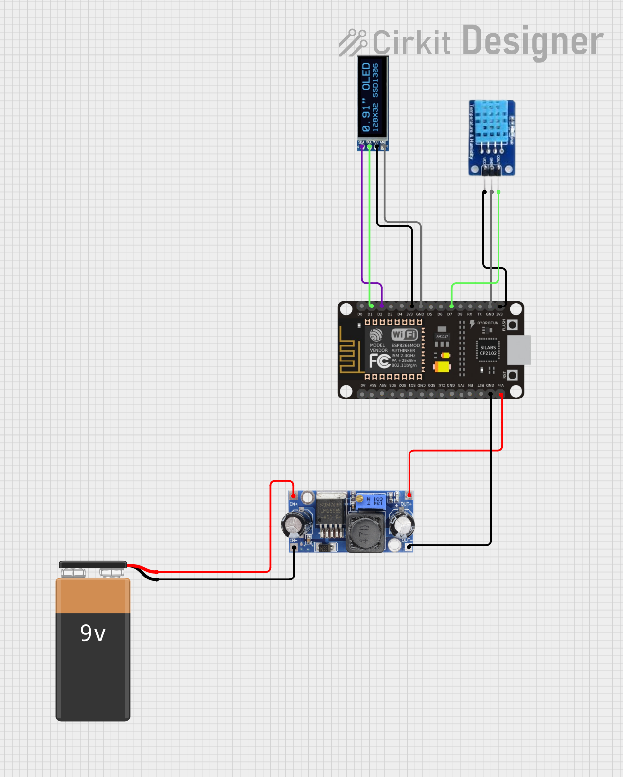
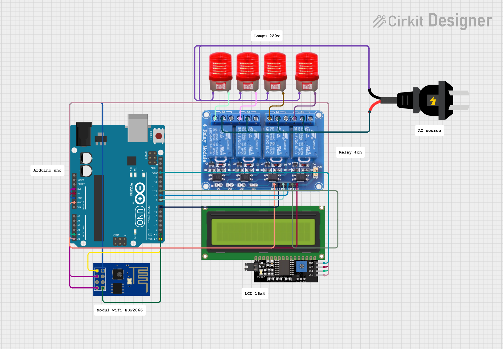

Explore Projects Built with ESP8266 WIFI
Common Applications and Use Cases
- Home automation systems
- Wireless sensor networks
- Smart appliances
- IoT prototyping and development
- Remote data logging and monitoring
- Wireless communication between devices
Technical Specifications
Key Technical Details
- Microcontroller: 32-bit Tensilica L106 running at 80 MHz (can be overclocked to 160 MHz)
- Operating Voltage: 3.0V to 3.6V
- Wi-Fi Standards: 802.11 b/g/n
- Flash Memory: 512 KB to 4 MB (varies by model)
- GPIO Pins: Up to 17 (depending on the module version)
- Communication Protocols: UART, SPI, I2C, PWM, ADC
- Power Consumption:
- Deep Sleep: ~10 µA
- Idle: ~70 mA
- Active: ~200 mA (transmitting)
- Operating Temperature: -40°C to 125°C
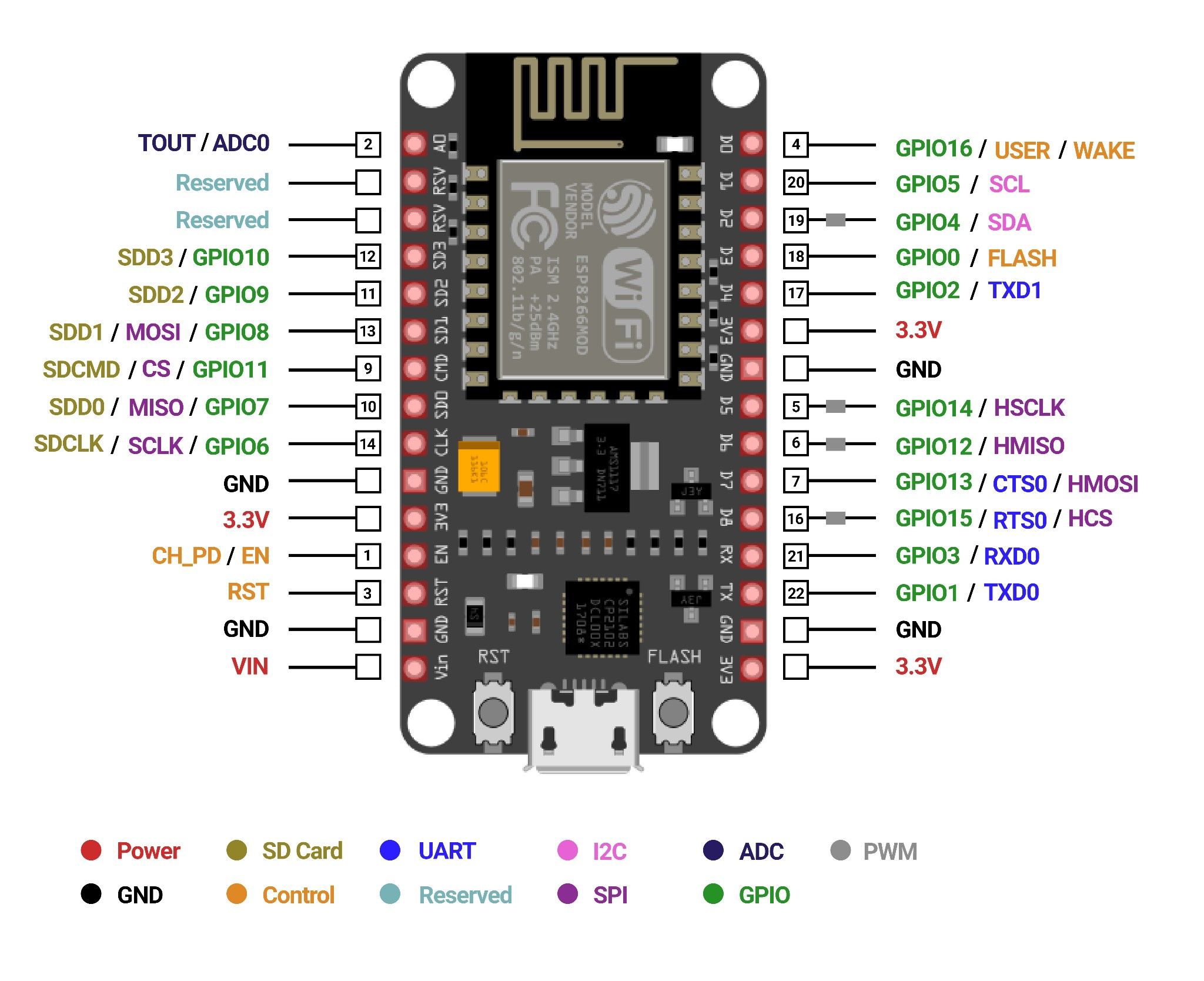
Pin Configuration and Descriptions
The ESP8266 is available in various module formats, such as ESP-01, ESP-12E, and NodeMCU. Below is the pin configuration for the ESP-12E module, one of the most commonly used versions.
| Pin | Name | Description |
|---|---|---|
| 1 | GND | Ground pin. Connect to the ground of the power supply. |
| 2 | GPIO0 | General-purpose I/O pin. Used for boot mode selection during startup. |
| 3 | GPIO2 | General-purpose I/O pin. |
| 4 | GPIO4 | General-purpose I/O pin. |
| 5 | GPIO5 | General-purpose I/O pin. |
| 6 | RXD | UART Receive pin. Used for serial communication. |
| 7 | TXD | UART Transmit pin. Used for serial communication. |
| 8 | CH_PD (EN) | Chip enable pin. Must be pulled high for the module to function. |
| 9 | VCC | Power supply pin. Connect to 3.3V. |
| 10 | RST | Reset pin. Pull low to reset the module. |
| 11 | ADC (A0) | Analog-to-digital converter input. Accepts voltages between 0V and 1V. |
| 12 | GPIO12 (MISO) | General-purpose I/O pin or SPI MISO (Master In Slave Out). |
| 13 | GPIO13 (MOSI) | General-purpose I/O pin or SPI MOSI (Master Out Slave In). |
| 14 | GPIO14 (SCLK) | General-purpose I/O pin or SPI clock. |
| 15 | GPIO15 (CS) | General-purpose I/O pin or SPI chip select. |
| 16 | GPIO16 | General-purpose I/O pin. Can also be used for deep sleep wake-up. |
Usage Instructions
How to Use the ESP8266 in a Circuit
- Power Supply: Ensure the ESP8266 is powered with a stable 3.3V supply. Do not exceed 3.6V, as this may damage the module.
- Connections:
- Connect the GND pin to the ground of your circuit.
- Connect the VCC pin to a 3.3V power source.
- Pull the CH_PD (EN) pin high (connect to 3.3V) to enable the module.
- Use the RXD and TXD pins for serial communication with a microcontroller or computer.
- Boot Mode Selection:
- For normal operation, pull GPIO0 high.
- For firmware flashing, pull GPIO0 low during power-up or reset.
- Programming: The ESP8266 can be programmed using the Arduino IDE or other tools like NodeMCU firmware. Use a USB-to-serial adapter for uploading code.
Important Considerations and Best Practices
- Use a level shifter or voltage divider if interfacing with 5V logic devices, as the ESP8266 operates at 3.3V logic levels.
- Add a decoupling capacitor (e.g., 10 µF) near the VCC and GND pins to stabilize the power supply.
- Avoid drawing excessive current from the GPIO pins. Use external transistors or relays for high-current loads.
- Ensure proper cooling if the module operates in high-temperature environments or under heavy Wi-Fi usage.
Example Code for Arduino UNO
Below is an example of using the ESP8266 to connect to a Wi-Fi network and send data to a server.
#include <ESP8266WiFi.h> // Include the ESP8266 WiFi library

// Replace with your network credentials
const char* ssid = "Your_SSID";
const char* password = "Your_PASSWORD";

void setup() {
  Serial.begin(115200); // Start serial communication at 115200 baud
  delay(10);

  // Connect to Wi-Fi
  Serial.println("Connecting to Wi-Fi...");
  WiFi.begin(ssid, password);

  while (WiFi.status() != WL_CONNECTED) {
    delay(500);
    Serial.print("."); // Print dots while connecting
  }

  Serial.println("\nWi-Fi connected!");
  Serial.print("IP Address: ");
  Serial.println(WiFi.localIP()); // Print the assigned IP address
}

void loop() {
  // Add your main code here
}
Troubleshooting and FAQs
Common Issues and Solutions
ESP8266 Not Responding:
- Ensure the CH_PD (EN) pin is pulled high.
- Verify the power supply is stable and provides sufficient current (at least 300 mA).
- Check the serial connection and baud rate settings.
Wi-Fi Connection Fails:
- Double-check the SSID and password.
- Ensure the router is within range and supports 2.4 GHz Wi-Fi (ESP8266 does not support 5 GHz).
Module Overheating:
- Verify the power supply voltage is within the 3.0V to 3.6V range.
- Reduce the Wi-Fi transmission power if possible.
GPIO Pins Not Working:
- Ensure the pins are not being used for other functions (e.g., boot mode selection).
- Avoid exceeding the maximum current rating of the GPIO pins.
FAQs
Can the ESP8266 operate as a standalone microcontroller? Yes, the ESP8266 has a built-in microcontroller and can run programs without an external MCU.
What is the maximum range of the ESP8266 Wi-Fi? The range depends on the environment but is typically around 50 meters indoors and 100 meters outdoors.
Can the ESP8266 connect to a 5 GHz Wi-Fi network? No, the ESP8266 only supports 2.4 GHz Wi-Fi networks.
How do I update the firmware on the ESP8266? Use tools like the ESP8266 Flasher or the Arduino IDE to upload new firmware via the UART interface.
This documentation provides a comprehensive guide to using the ESP8266 Wi-Fi module effectively in your projects.