Cirkit Designer Logo
Cirkit Designer
Your all-in-one circuit design IDE
Home / 
Component Documentation

How to Use Flush Switch: Examples, Pinouts, and Specs

Image of Flush Switch
Cirkit Designer LogoDesign with Flush Switch in Cirkit Designer

Introduction

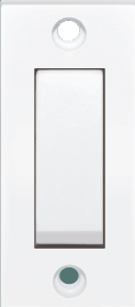
A flush switch is a momentary tactile switch that is commonly used in electronic circuits. Its design allows it to be mounted so that its surface is flush with the panel or board, providing a sleek and unobtrusive appearance. When pressed, the switch momentarily makes or breaks an electrical connection, which can be used to control various aspects of a circuit such as turning on a light, starting a process, or inputting a signal to a microcontroller.

Explore Projects Built with Flush Switch

Use Cirkit Designer to design, explore, and prototype these projects online. Some projects support real-time simulation. Click "Open Project" to start designing instantly!
Flush Switch Controlled Lamp Circuit with AC Power Supply and MCB Protection
Image of LAMP CONTROLE WITH MCB: A project utilizing Flush Switch in a practical application
This circuit is designed to control a lamp using a flush switch and is protected by two MCBs (Miniature Circuit Breakers). The AC supply is connected to the input of the first MCB, whose output is connected to the flush switch. The flush switch then controls the power to the lamp, with the second MCB placed in the neutral line for additional safety.
Cirkit Designer LogoOpen Project in Cirkit Designer
AC Bulb Control Circuit with Flush Switch and MCB Protection
Image of LAMP CONTROLE WITH MCB 1: A project utilizing Flush Switch in a practical application
This circuit is designed to control an AC bulb using a flush switch. The AC power supply is connected through an MCB (Miniature Circuit Breaker) for protection, and the flush switch acts as an on/off control for the bulb. There is no microcontroller or embedded code involved in this simple power control circuit.
Cirkit Designer LogoOpen Project in Cirkit Designer
Toggle Switch Controlled Lamp Circuit with Banana Sockets
Image of STAIRCASE: A project utilizing Flush Switch in a practical application
This circuit consists of two toggle switches and a red lamp connected to panel mount banana sockets. The switches control the connection between the red and black banana sockets, allowing the lamp to be turned on or off depending on the switch positions.
Cirkit Designer LogoOpen Project in Cirkit Designer
ESP32 and SIM900A Based Smart Home Automation with Wi-Fi and GSM Control
Image of iot: A project utilizing Flush Switch in a practical application
This circuit features an ESP32 microcontroller interfaced with multiple flush switches and two 4-channel relay modules to control various loads. It also includes a SIM900A module for GSM communication and an AC to DC converter for power management. The ESP32 handles input from the switches and controls the relays, while the SIM900A provides remote communication capabilities.
Cirkit Designer LogoOpen Project in Cirkit Designer

Explore Projects Built with Flush Switch

Use Cirkit Designer to design, explore, and prototype these projects online. Some projects support real-time simulation. Click "Open Project" to start designing instantly!
Image of LAMP CONTROLE WITH MCB: A project utilizing Flush Switch in a practical application
Flush Switch Controlled Lamp Circuit with AC Power Supply and MCB Protection
This circuit is designed to control a lamp using a flush switch and is protected by two MCBs (Miniature Circuit Breakers). The AC supply is connected to the input of the first MCB, whose output is connected to the flush switch. The flush switch then controls the power to the lamp, with the second MCB placed in the neutral line for additional safety.
Cirkit Designer LogoOpen Project in Cirkit Designer
Image of LAMP CONTROLE WITH MCB 1: A project utilizing Flush Switch in a practical application
AC Bulb Control Circuit with Flush Switch and MCB Protection
This circuit is designed to control an AC bulb using a flush switch. The AC power supply is connected through an MCB (Miniature Circuit Breaker) for protection, and the flush switch acts as an on/off control for the bulb. There is no microcontroller or embedded code involved in this simple power control circuit.
Cirkit Designer LogoOpen Project in Cirkit Designer
Image of STAIRCASE: A project utilizing Flush Switch in a practical application
Toggle Switch Controlled Lamp Circuit with Banana Sockets
This circuit consists of two toggle switches and a red lamp connected to panel mount banana sockets. The switches control the connection between the red and black banana sockets, allowing the lamp to be turned on or off depending on the switch positions.
Cirkit Designer LogoOpen Project in Cirkit Designer
Image of iot: A project utilizing Flush Switch in a practical application
ESP32 and SIM900A Based Smart Home Automation with Wi-Fi and GSM Control
This circuit features an ESP32 microcontroller interfaced with multiple flush switches and two 4-channel relay modules to control various loads. It also includes a SIM900A module for GSM communication and an AC to DC converter for power management. The ESP32 handles input from the switches and controls the relays, while the SIM900A provides remote communication capabilities.
Cirkit Designer LogoOpen Project in Cirkit Designer

Common Applications and Use Cases

  • User input for electronic devices
  • Reset or interrupt buttons on printed circuit boards
  • Doorbell or intercom systems
  • Keyboard keys or game controller buttons
  • Prototype and hobbyist projects, often interfaced with microcontrollers like Arduino

Technical Specifications

Key Technical Details

  • Switch Type: Momentary tactile switch
  • Contact Configuration: Normally open (NO)
  • Actuation Force: Typically between 100g to 300g
  • Rated Voltage: Often 12V DC
  • Rated Current: Usually around 50mA
  • Operating Temperature Range: -20°C to 70°C

Pin Configuration and Descriptions

Pin Number Description
1 Normally Open (NO)
2 Common (COM)

Note: The pin configuration may vary depending on the specific model of the flush switch. Always refer to the manufacturer's datasheet for exact details.

Usage Instructions

How to Use the Flush Switch in a Circuit

  1. Identify the Pins: Locate the Normally Open (NO) and Common (COM) pins on the switch.
  2. Circuit Integration: Connect the Common (COM) pin to one side of the power source or signal line.
  3. Load Connection: Connect the Normally Open (NO) pin to the load (e.g., LED, relay, microcontroller input pin).
  4. Mounting: Secure the switch in place so that it is flush with the panel or board surface.
  5. Testing: Press the switch to ensure it momentarily closes the circuit, activating the load.

Important Considerations and Best Practices

  • Ensure the switch's voltage and current ratings are not exceeded by the circuit.
  • Use a pull-up or pull-down resistor when connecting to a microcontroller to ensure a stable signal.
  • Avoid excessive force to prevent damage to the switch mechanism.
  • Consider the environmental conditions where the switch will be used and ensure it meets the operating temperature range.

Troubleshooting and FAQs

Common Issues

  • Switch Does Not Actuate: Check for proper mounting and that the actuation force is sufficient.
  • Intermittent Connection: Inspect for loose wiring or solder joints.
  • No Response in Circuit: Verify that the switch's ratings match the circuit requirements.

Solutions and Tips for Troubleshooting

  • Double-check the wiring against the circuit diagram.
  • Test the switch with a multimeter to ensure it is functioning correctly.
  • Replace the switch if it shows signs of physical damage or wear.

FAQs

Q: Can I use a flush switch with an AC circuit? A: While some flush switches may be rated for low-voltage AC applications, always check the manufacturer's specifications before use.

Q: How do I know if the switch is momentary? A: A momentary switch will only maintain its closed state while being pressed and will return to its open state upon release.

Q: What is the lifespan of a flush switch? A: The lifespan can vary, but many are rated for hundreds of thousands of cycles. Check the datasheet for the specific model.

Example Code for Arduino UNO

// Define the pin connected to the flush switch
const int flushSwitchPin = 2;

void setup() {
  // Set the flush switch pin as an input with an internal pull-up resistor
  pinMode(flushSwitchPin, INPUT_PULLUP);
  // Initialize serial communication at 9600 bits per second
  Serial.begin(9600);
}

void loop() {
  // Check the state of the switch
  int switchState = digitalRead(flushSwitchPin);
  
  // If the switch is pressed (circuit closed), the pin reads LOW
  if (switchState == LOW) {
    Serial.println("Switch Pressed");
    // Add code here to respond to switch press
  } else {
    // Add code here to respond to switch release
  }
  
  // Debounce delay to avoid reading noise as multiple presses
  delay(50);
}

Note: The above code assumes the use of an internal pull-up resistor. When the switch is pressed, the pin is connected to ground, resulting in a LOW reading.

This documentation provides a comprehensive overview of the flush switch, its specifications, usage, and troubleshooting. For specific projects or advanced applications, always refer to the datasheet and additional resources provided by the manufacturer.