Cirkit Designer Logo
Cirkit Designer
Your all-in-one circuit design IDE
Home / 
Component Documentation

How to Use Adafruit Push Button Powerswitch: Examples, Pinouts, and Specs

Image of Adafruit Push Button Powerswitch
Cirkit Designer LogoDesign with Adafruit Push Button Powerswitch in Cirkit Designer

Introduction

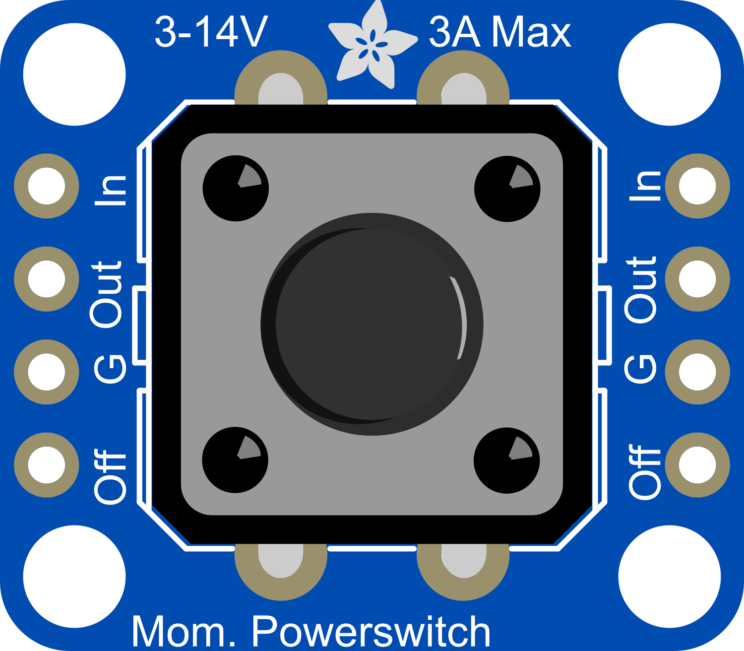
The Adafruit Push Button Power Switch is a compact and convenient electronic component designed to control the power flow to your project with the ease of a push button. This board is particularly useful for projects that require a clean and simple method to turn on and off without the need for complex circuitry. Common applications include hobbyist projects, portable electronics, and any system that benefits from a user-friendly power interface.

Explore Projects Built with Adafruit Push Button Powerswitch

Use Cirkit Designer to design, explore, and prototype these projects online. Some projects support real-time simulation. Click "Open Project" to start designing instantly!
Battery-Powered Multi-Button Controller with Seeed Studio nRF52840
Image of RetroBle Atari Controller: A project utilizing Adafruit Push Button Powerswitch in a practical application
This circuit consists of five pushbuttons connected to a Seeed Studio nRF52840 microcontroller, which is powered by a Polymer Lithium Ion Battery. Each pushbutton is connected to a different GPIO pin on the microcontroller, allowing for individual button press detection and processing.
Cirkit Designer LogoOpen Project in Cirkit Designer
Raspberry Pi 5 Pushbutton Input Circuit
Image of lab 1: A project utilizing Adafruit Push Button Powerswitch in a practical application
This circuit features a Raspberry Pi 5 connected to a pushbutton. The pushbutton is powered by the 3.3V pin of the Raspberry Pi and its output is connected to GPIO 15, allowing the Raspberry Pi to detect button presses.
Cirkit Designer LogoOpen Project in Cirkit Designer
ESP32-Based Portable NFC/RFID Reader with OLED Interface
Image of omnitool: A project utilizing Adafruit Push Button Powerswitch in a practical application
This circuit features an ESP32 microcontroller connected to a 0.96" OLED display via I2C (SCK and SDA lines), multiple pushbuttons interfaced to various GPIO pins for input, and a LiPoly battery connected through a TP4056 charging/protection module to power the system. A step-up boost power converter adjusts the battery voltage to supply the ESP32 and OLED display. The toggle switch controls the power flow from the battery to the converter, enabling an on/off functionality for the circuit.
Cirkit Designer LogoOpen Project in Cirkit Designer
Battery-Powered LED Circuit with Pushbutton Control and Capacitance Smoothing
Image of Coding and Robotics activity 3: A project utilizing Adafruit Push Button Powerswitch in a practical application
This circuit consists of a 4 x AAA battery mount providing power, two pushbuttons acting as switches, an electrolytic capacitor for smoothing voltage fluctuations, and a red LED as an indicator. The LED lights up when either pushbutton is pressed, with the capacitor likely serving to debounce the pushbutton signal or provide a more stable LED operation. There is no microcontroller in this circuit, indicating a simple, direct-control user interface.
Cirkit Designer LogoOpen Project in Cirkit Designer

Explore Projects Built with Adafruit Push Button Powerswitch

Use Cirkit Designer to design, explore, and prototype these projects online. Some projects support real-time simulation. Click "Open Project" to start designing instantly!
Image of RetroBle Atari Controller: A project utilizing Adafruit Push Button Powerswitch in a practical application
Battery-Powered Multi-Button Controller with Seeed Studio nRF52840
This circuit consists of five pushbuttons connected to a Seeed Studio nRF52840 microcontroller, which is powered by a Polymer Lithium Ion Battery. Each pushbutton is connected to a different GPIO pin on the microcontroller, allowing for individual button press detection and processing.
Cirkit Designer LogoOpen Project in Cirkit Designer
Image of lab 1: A project utilizing Adafruit Push Button Powerswitch in a practical application
Raspberry Pi 5 Pushbutton Input Circuit
This circuit features a Raspberry Pi 5 connected to a pushbutton. The pushbutton is powered by the 3.3V pin of the Raspberry Pi and its output is connected to GPIO 15, allowing the Raspberry Pi to detect button presses.
Cirkit Designer LogoOpen Project in Cirkit Designer
Image of omnitool: A project utilizing Adafruit Push Button Powerswitch in a practical application
ESP32-Based Portable NFC/RFID Reader with OLED Interface
This circuit features an ESP32 microcontroller connected to a 0.96" OLED display via I2C (SCK and SDA lines), multiple pushbuttons interfaced to various GPIO pins for input, and a LiPoly battery connected through a TP4056 charging/protection module to power the system. A step-up boost power converter adjusts the battery voltage to supply the ESP32 and OLED display. The toggle switch controls the power flow from the battery to the converter, enabling an on/off functionality for the circuit.
Cirkit Designer LogoOpen Project in Cirkit Designer
Image of Coding and Robotics activity 3: A project utilizing Adafruit Push Button Powerswitch in a practical application
Battery-Powered LED Circuit with Pushbutton Control and Capacitance Smoothing
This circuit consists of a 4 x AAA battery mount providing power, two pushbuttons acting as switches, an electrolytic capacitor for smoothing voltage fluctuations, and a red LED as an indicator. The LED lights up when either pushbutton is pressed, with the capacitor likely serving to debounce the pushbutton signal or provide a more stable LED operation. There is no microcontroller in this circuit, indicating a simple, direct-control user interface.
Cirkit Designer LogoOpen Project in Cirkit Designer

Technical Specifications

Key Technical Details

  • Input Voltage: 3.3V to 14V DC
  • Output Current: Up to 2A
  • Control Method: Push button
  • Indicators: Onboard LED for power status
  • Dimensions: 0.6" x 0.6" x 0.2" inches (approx.)

Pin Configuration and Descriptions

Pin Name Description
Vin Voltage input (3.3V to 14V DC)
GND Ground
Vout Voltage output (controlled by the push button)
A Anode of the onboard LED
K Cathode of the onboard LED

Usage Instructions

Incorporating into a Circuit

To use the Adafruit Push Button Power Switch in a circuit, follow these steps:

  1. Connect the Vin pin to the positive terminal of your power source.
  2. Connect the GND pin to the ground terminal of your power source.
  3. Connect the Vout pin to the power input of your load (e.g., a microcontroller, motor, etc.).
  4. The onboard LED is optional for use. If you wish to use it, connect the A pin to Vin and the K pin to GND.

Best Practices

  • Ensure that the power source does not exceed the maximum voltage rating of 14V DC.
  • Do not draw more than 2A of current through the switch to prevent damage.
  • Use a pull-up or pull-down resistor on the Vout line if your load does not have one internally to prevent floating states when the switch is off.

Example Code for Arduino UNO

// Example code to control an LED using the Adafruit Push Button Power Switch
const int ledPin = 13; // LED connected to digital pin 13

void setup() {
  pinMode(ledPin, OUTPUT); // sets the digital pin as output
}

void loop() {
  // The LED will be controlled by the state of the Push Button Power Switch
  // When the button is pressed, the power switch will turn on and the LED will light up
  // When the button is pressed again, the power switch will turn off and the LED will turn off
  digitalWrite(ledPin, HIGH); // sets the LED on
  delay(1000);                // waits for a second
  digitalWrite(ledPin, LOW);  // sets the LED off
  delay(1000);                // waits for a second
}

Note: This example assumes that the Arduino is powered through the Adafruit Push Button Power Switch. The ledPin is used as an indicator and can be replaced with any other load you wish to control.

Troubleshooting and FAQs

Common Issues

  • Power Switch Does Not Turn On: Ensure that the input voltage is within the specified range and that all connections are secure.
  • Load Does Not Operate: Check if the current draw of the load exceeds the 2A limit. Also, verify that the load is properly connected to the Vout pin.
  • LED Indicator Not Working: Confirm that the LED pins (A and K) are correctly connected to Vin and GND, respectively.

Solutions and Tips

  • If the power switch seems unresponsive, double-check the wiring, especially the Vin and GND connections.
  • For loads that require a stable output, consider adding a capacitor across the Vout and GND pins to smooth out any voltage spikes.
  • If the onboard LED is too bright or not necessary, you can omit the connection or add a resistor in series to limit the current.

FAQs

Q: Can I use the power switch with a voltage lower than 3.3V? A: The power switch is designed to operate within the 3.3V to 14V range. Using it below 3.3V may result in unreliable performance.

Q: Is it possible to control the power switch programmatically? A: The power switch is designed for manual operation via the push button. To control power programmatically, you would need to use a different component, such as a relay or a transistor switch controlled by a microcontroller.

Q: How do I know if the power switch is on or off? A: The onboard LED indicator will light up when the power switch is in the 'on' state, providing a visual cue of the power status.