How to Use Adafruit LIS3MDL Triple-axis Magnetometer: Examples, Pinouts, and Specs
Introduction
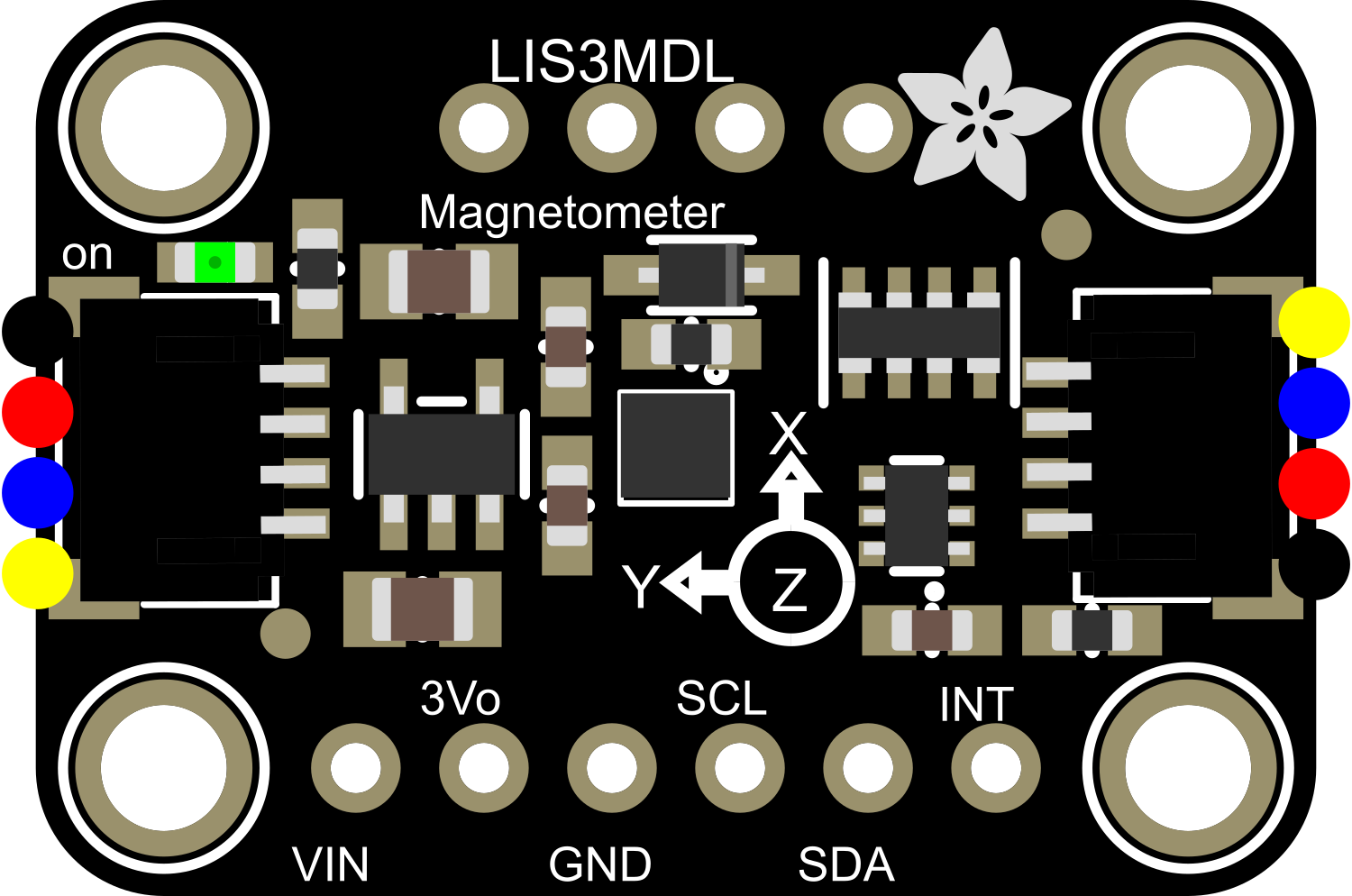
The Adafruit LIS3MDL Triple-axis Magnetometer is a compact and versatile sensor capable of measuring magnetic fields in three dimensions. It is designed to be used in a wide range of applications, including mobile phones, tablets, drones, and particularly for compass functionalities in navigation systems. The LIS3MDL is an ideal choice for projects requiring precise heading information or for detecting magnetic anomalies.
Explore Projects Built with Adafruit LIS3MDL Triple-axis Magnetometer
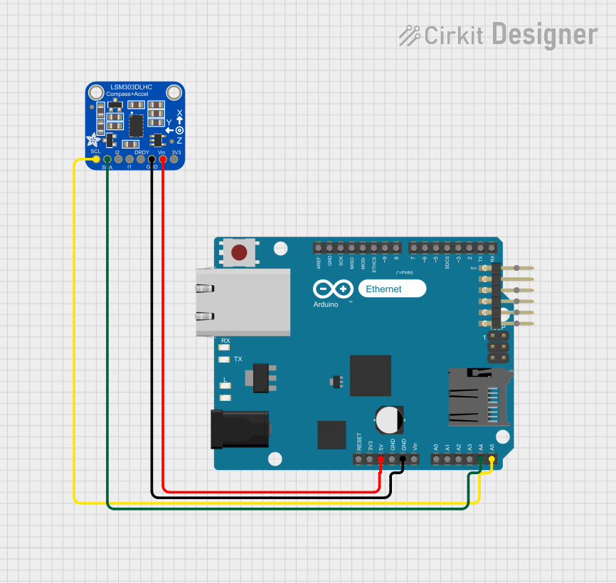

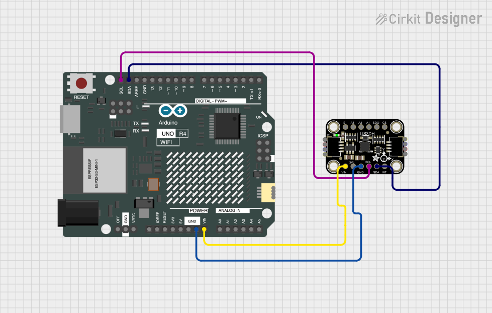
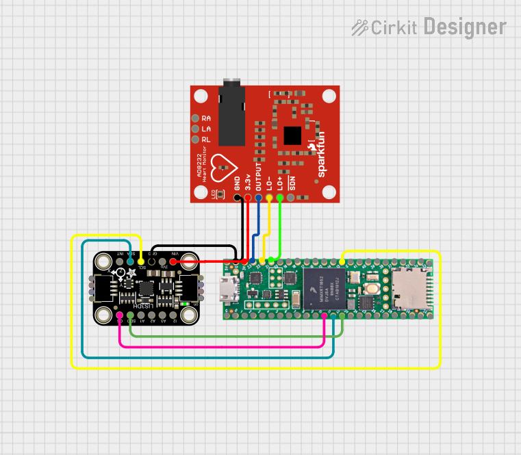
Explore Projects Built with Adafruit LIS3MDL Triple-axis Magnetometer
Technical Specifications
Key Features
- Magnetic field range: ±4/±8/±12/±16 gauss
- Digital output: I²C/SPI
- 16-bit data output
- Power supply range: 2.5V to 5.5V
- Low power consumption
- Operating temperature range: -40°C to +85°C
Pin Configuration and Descriptions
| Pin Number | Name | Description |
|---|---|---|
| 1 | VIN | Supply voltage (2.5V to 5.5V) |
| 2 | GND | Ground |
| 3 | SDA | I²C Data / SPI Serial Data In (SDI) |
| 4 | SCL | I²C Clock / SPI Serial Clock (SCK) |
| 5 | SDO | SPI Serial Data Out (SDO) / I²C Address Selection |
| 6 | CS | SPI Chip Select (Active Low) |
Usage Instructions
Integration into a Circuit
To use the Adafruit LIS3MDL Triple-axis Magnetometer in a circuit:
- Connect the VIN pin to a 2.5V to 5.5V power supply.
- Connect the GND pin to the ground of your power supply.
- For I²C communication, connect the SDA and SCL pins to your microcontroller's I²C data and clock lines, respectively.
- For SPI communication, connect the SDA, SCL, SDO, and CS pins to your microcontroller's SPI data in, clock, data out, and chip select lines.
Best Practices
- Ensure that the power supply is stable and within the specified voltage range.
- Use pull-up resistors on the I²C lines if they are not already present on the microcontroller board.
- Keep the magnetometer away from strong magnetic fields that could saturate the sensor and affect readings.
- When using SPI, ensure that the CS pin is toggled correctly to avoid communication issues.
Example Code for Arduino UNO
Below is an example code snippet for interfacing the Adafruit LIS3MDL with an Arduino UNO using the I²C protocol. Before using the code, make sure to install the Adafruit LIS3MDL library through the Arduino Library Manager.
#include <Wire.h>
#include <Adafruit_Sensor.h>
#include <Adafruit_LIS3MDL.h>

Adafruit_LIS3MDL lis3mdl = Adafruit_LIS3MDL();

void setup() {
  Serial.begin(9600);
  while (!Serial) { delay(10); } // Wait for serial monitor to open

  Serial.println("LIS3MDL Magnetometer Test");

  if (!lis3mdl.begin_I2C()) { // Initialize the sensor for I²C
    Serial.println("Failed to find LIS3MDL chip");
    while (1) { delay(10); }
  }

  Serial.println("LIS3MDL Found!");
}

void loop() {
  lis3mdl.read(); // Get new data from the sensor

  Serial.print("X: "); Serial.print(lis3mdl.x);
  Serial.print(" Y: "); Serial.print(lis3mdl.y);
  Serial.print(" Z: "); Serial.print(lis3mdl.z);

  Serial.println(" uT"); // Microteslas

  delay(500); // Wait half a second between readings
}
Troubleshooting and FAQs
Common Issues
- Inaccurate Readings: Ensure that the sensor is calibrated correctly and that there are no nearby magnetic sources interfering with the measurements.
- No Communication: Check the wiring, ensure that the correct I²C address or SPI settings are used, and that the library is installed properly.
FAQs
Q: Can the LIS3MDL be used for detecting metals? A: The LIS3MDL is designed to measure magnetic fields and can detect ferromagnetic materials that affect those fields, but it is not a metal detector per se.
Q: How do I calibrate the magnetometer? A: Calibration typically involves rotating the sensor in various orientations and using the collected data to offset any biases. Adafruit provides a guide and example code for calibration.
Q: What is the default I²C address of the LIS3MDL? A: The default I²C address is 0x1C, but it can be changed to 0x1E by connecting the SDO pin to the supply voltage.
For further assistance, consult the Adafruit LIS3MDL datasheet and the Adafruit support forums.