
How to Use ENCODER_RGB_CA: Examples, Pinouts, and Specs
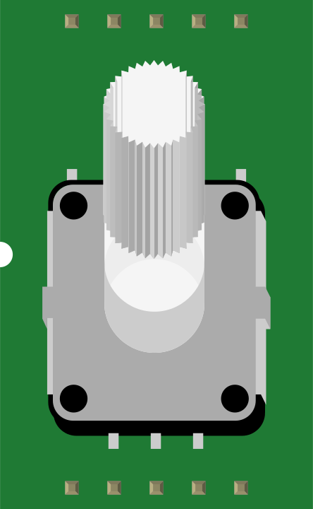
 Design with ENCODER_RGB_CA in Cirkit Designer
Introduction
The ENCODER_RGB_CA is an RGB encoder designed to convert analog color signals into a digital format. This component is commonly used in video processing and display applications, where it ensures accurate and efficient color signal conversion for digital systems. Its compact design and high performance make it ideal for use in televisions, video capture devices, and multimedia systems.
Explore Projects Built with ENCODER_RGB_CA
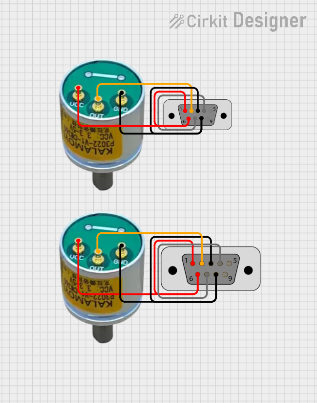 Open Project in Cirkit Designer
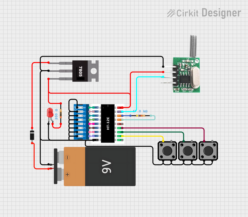 Open Project in Cirkit Designer
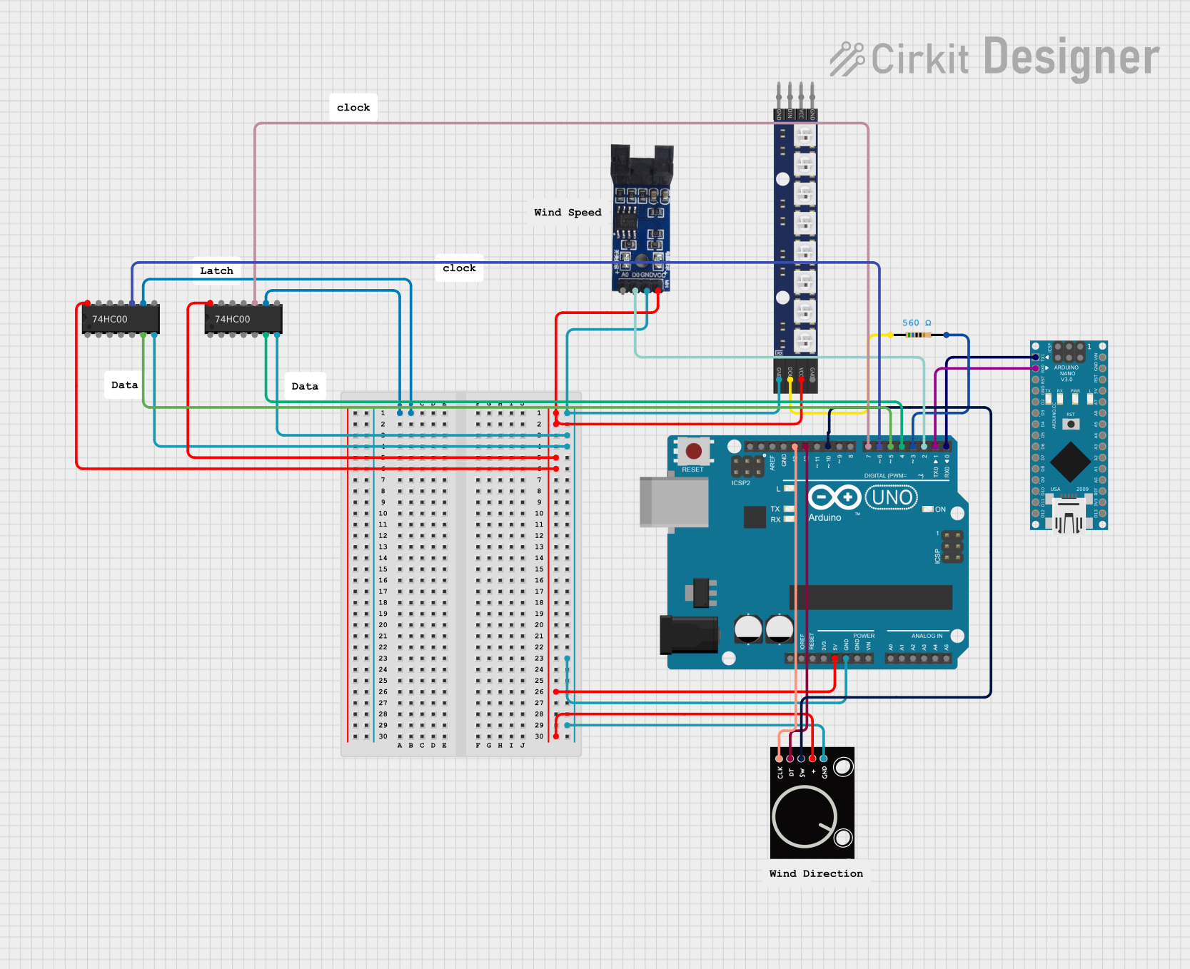 Open Project in Cirkit Designer
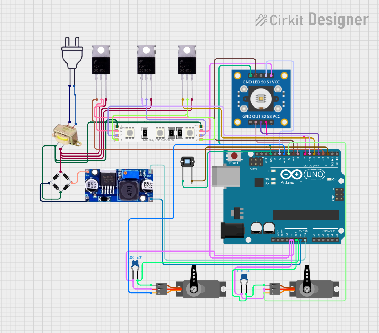 Open Project in Cirkit Designer
Explore Projects Built with ENCODER_RGB_CA
Open Project in Cirkit DesignerOpen Project in Cirkit DesignerOpen Project in Cirkit DesignerOpen Project in Cirkit DesignerCommon Applications
- Video signal processing in televisions and monitors
- Digital video capture and recording devices
- Multimedia systems requiring analog-to-digital color conversion
- Gaming consoles and video streaming hardware
Technical Specifications
The ENCODER_RGB_CA is designed to handle a wide range of input signals and provide reliable digital output. Below are its key technical specifications:
General Specifications
| Parameter | Value |
|---|---|
| Input Voltage (Vcc) | 3.3V to 5V |
| Operating Current | 50mA (typical) |
| Input Signal Type | Analog RGB (Red, Green, Blue) |
| Output Signal Type | Digital RGB (8-bit per channel) |
| Operating Temperature | -20°C to 85°C |
| Package Type | 16-pin DIP or SMD |
Pin Configuration
The ENCODER_RGB_CA has a 16-pin configuration. The table below describes each pin:
| Pin Number | Pin Name | Description |
|---|---|---|
| 1 | VCC | Power supply input (3.3V to 5V) |
| 2 | GND | Ground connection |
| 3 | R_IN | Red channel analog input |
| 4 | G_IN | Green channel analog input |
| 5 | B_IN | Blue channel analog input |
| 6 | HSYNC | Horizontal sync input |
| 7 | VSYNC | Vertical sync input |
| 8 | CLK | Clock input for synchronization |
| 9 | R_OUT | Red channel digital output |
| 10 | G_OUT | Green channel digital output |
| 11 | B_OUT | Blue channel digital output |
| 12 | HSYNC_OUT | Horizontal sync digital output |
| 13 | VSYNC_OUT | Vertical sync digital output |
| 14 | ENABLE | Enable pin (active high) |
| 15 | TEST | Test mode pin (leave unconnected for normal use) |
| 16 | NC | No connection |
Usage Instructions
To use the ENCODER_RGB_CA in a circuit, follow these steps:
- Power Supply: Connect the VCC pin to a stable 3.3V or 5V power source and the GND pin to ground.
- Input Signals: Provide analog RGB signals to the R_IN, G_IN, and B_IN pins. Ensure the input signals are within the acceptable voltage range (0V to VCC).
- Synchronization: Connect the HSYNC and VSYNC pins to the horizontal and vertical sync signals of the input source. These signals are critical for proper timing and synchronization.
- Clock Signal: Provide a clock signal to the CLK pin. The clock frequency should match the requirements of your application.
- Enable the Encoder: Set the ENABLE pin high to activate the encoder. If this pin is low, the encoder will remain in a disabled state.
- Output Signals: The digital RGB signals will be available on the R_OUT, G_OUT, and B_OUT pins. Similarly, the HSYNC_OUT and VSYNC_OUT pins will provide synchronized digital sync signals.
Important Considerations
- Use decoupling capacitors (e.g., 0.1µF) near the VCC pin to reduce noise and ensure stable operation.
- Ensure proper grounding to avoid signal interference.
- Avoid leaving unused input pins floating; connect them to ground if not in use.
- For testing purposes, the TEST pin can be used, but it should remain unconnected during normal operation.
Example: Connecting to an Arduino UNO
The ENCODER_RGB_CA can be interfaced with an Arduino UNO to process analog RGB signals. Below is an example code snippet to read the digital output signals:
// Define the digital input pins for the RGB encoder
const int redPin = 2;    // Pin connected to R_OUT
const int greenPin = 3;  // Pin connected to G_OUT
const int bluePin = 4;   // Pin connected to B_OUT

void setup() {
  // Initialize serial communication for debugging
  Serial.begin(9600);

  // Set the RGB pins as inputs
  pinMode(redPin, INPUT);
  pinMode(greenPin, INPUT);
  pinMode(bluePin, INPUT);
}

void loop() {
  // Read the digital RGB values
  int redValue = digitalRead(redPin);
  int greenValue = digitalRead(greenPin);
  int blueValue = digitalRead(bluePin);

  // Print the RGB values to the serial monitor
  Serial.print("Red: ");
  Serial.print(redValue);
  Serial.print(", Green: ");
  Serial.print(greenValue);
  Serial.print(", Blue: ");
  Serial.println(blueValue);

  // Add a small delay for stability
  delay(100);
}
Troubleshooting and FAQs
Common Issues
No Output Signals:
- Ensure the ENABLE pin is set high.
- Verify that the input signals are within the specified voltage range.
- Check the power supply and ground connections.
Distorted Output:
- Verify the clock signal frequency and ensure it matches the application requirements.
- Check for noise or interference in the input signals.
Sync Issues:
- Ensure the HSYNC and VSYNC signals are properly connected and synchronized with the input source.
FAQs
Q: Can the ENCODER_RGB_CA handle YUV signals?
A: No, the ENCODER_RGB_CA is specifically designed for RGB signals. For YUV signals, a different encoder is required.
Q: What is the maximum clock frequency supported?
A: The maximum clock frequency is 25MHz. Ensure your clock source does not exceed this limit.
Q: Can I leave the TEST pin connected during normal operation?
A: No, the TEST pin should remain unconnected during normal operation to avoid unintended behavior.
Q: Is the component compatible with 3.3V systems?
A: Yes, the ENCODER_RGB_CA operates with both 3.3V and 5V power supplies, making it compatible with a wide range of systems.