How to Use ZK-BM1 10A MOTOR DRIVER: Examples, Pinouts, and Specs
Introduction
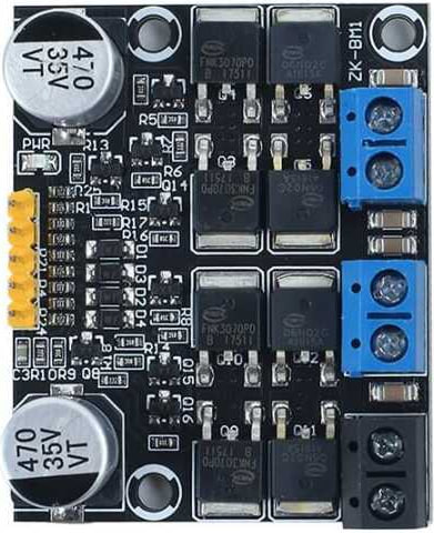
The ZK-BM1 10A Motor Driver, manufactured by ZIQQU, is a high-power motor driver designed to handle up to 10A of current. This component is ideal for controlling the speed and direction of DC motors in various applications, including robotics, automation systems, and electric vehicles. Its robust design ensures reliable performance in demanding environments.
Explore Projects Built with ZK-BM1 10A MOTOR DRIVER


Explore Projects Built with ZK-BM1 10A MOTOR DRIVER
Technical Specifications
Key Technical Details
| Parameter | Value |
|---|---|
| Manufacturer | ZIQQU |
| Part ID | ZK-BM1 |
| Maximum Current | 10A |
| Operating Voltage | 6V - 30V |
| Control Signal | PWM (Pulse Width Modulation) |
| Dimensions | 60mm x 45mm x 20mm |
| Weight | 50g |
Pin Configuration and Descriptions
| Pin Number | Pin Name | Description |
|---|---|---|
| 1 | VCC | Power supply input (6V - 30V) |
| 2 | GND | Ground |
| 3 | IN1 | Control signal input 1 (PWM) |
| 4 | IN2 | Control signal input 2 (PWM) |
| 5 | OUT1 | Motor output 1 |
| 6 | OUT2 | Motor output 2 |
Usage Instructions
How to Use the Component in a Circuit
- Power Supply Connection: Connect the VCC pin to a power supply ranging from 6V to 30V. Connect the GND pin to the ground of the power supply.
- Control Signal Connection: Connect the IN1 and IN2 pins to the PWM output pins of a microcontroller (e.g., Arduino UNO).
- Motor Connection: Connect the motor terminals to the OUT1 and OUT2 pins.
- PWM Control: Use PWM signals on IN1 and IN2 to control the speed and direction of the motor.
Important Considerations and Best Practices
- Ensure that the power supply voltage is within the specified range (6V - 30V).
- Use appropriate heat sinks or cooling mechanisms if the motor driver is operating near its maximum current rating (10A).
- Avoid short circuits between the motor output pins (OUT1 and OUT2) to prevent damage to the driver.
- Use proper decoupling capacitors near the power supply pins to minimize noise and voltage spikes.
Example Code for Arduino UNO
// Example code to control the ZK-BM1 10A Motor Driver with Arduino UNO

const int IN1 = 9; // PWM pin connected to IN1
const int IN2 = 10; // PWM pin connected to IN2

void setup() {
  pinMode(IN1, OUTPUT); // Set IN1 as an output
  pinMode(IN2, OUTPUT); // Set IN2 as an output
}

void loop() {
  // Rotate motor in one direction
  analogWrite(IN1, 255); // Set IN1 to maximum PWM value (full speed)
  analogWrite(IN2, 0); // Set IN2 to 0 (stop)
  delay(2000); // Run for 2 seconds

  // Stop the motor
  analogWrite(IN1, 0); // Set IN1 to 0 (stop)
  analogWrite(IN2, 0); // Set IN2 to 0 (stop)
  delay(1000); // Wait for 1 second

  // Rotate motor in the opposite direction
  analogWrite(IN1, 0); // Set IN1 to 0 (stop)
  analogWrite(IN2, 255); // Set IN2 to maximum PWM value (full speed)
  delay(2000); // Run for 2 seconds

  // Stop the motor
  analogWrite(IN1, 0); // Set IN1 to 0 (stop)
  analogWrite(IN2, 0); // Set IN2 to 0 (stop)
  delay(1000); // Wait for 1 second
}
Troubleshooting and FAQs
Common Issues Users Might Face
Motor Not Running:
- Solution: Check the power supply connections and ensure the voltage is within the specified range. Verify that the control signals (PWM) are correctly connected and configured.
Motor Running in One Direction Only:
- Solution: Ensure that both IN1 and IN2 are receiving the correct PWM signals. Check for any loose connections or damaged wires.
Overheating:
- Solution: Ensure proper cooling mechanisms are in place. Reduce the load on the motor or use a heat sink to dissipate heat.
Noise and Voltage Spikes:
- Solution: Use decoupling capacitors near the power supply pins to minimize noise. Ensure that the power supply is stable and free from significant fluctuations.
FAQs
Can I use the ZK-BM1 with a 5V power supply?
- No, the minimum operating voltage for the ZK-BM1 is 6V. Using a 5V power supply may result in improper operation or damage to the driver.
What type of motors can I control with the ZK-BM1?
- The ZK-BM1 is designed to control DC motors. Ensure that the motor's current rating does not exceed 10A.
How do I control the speed of the motor?
- Use PWM signals on the IN1 and IN2 pins to control the speed of the motor. Varying the duty cycle of the PWM signal will change the motor speed.
Can I control the direction of the motor?
- Yes, by changing the PWM signals on IN1 and IN2, you can control the direction of the motor. Setting IN1 high and IN2 low will rotate the motor in one direction, while setting IN1 low and IN2 high will rotate it in the opposite direction.
This documentation provides a comprehensive guide to using the ZK-BM1 10A Motor Driver. By following the instructions and best practices outlined, users can effectively integrate this component into their projects and achieve reliable motor control.