How to Use ESP32 WLED Digital LED Controller: Examples, Pinouts, and Specs
Introduction
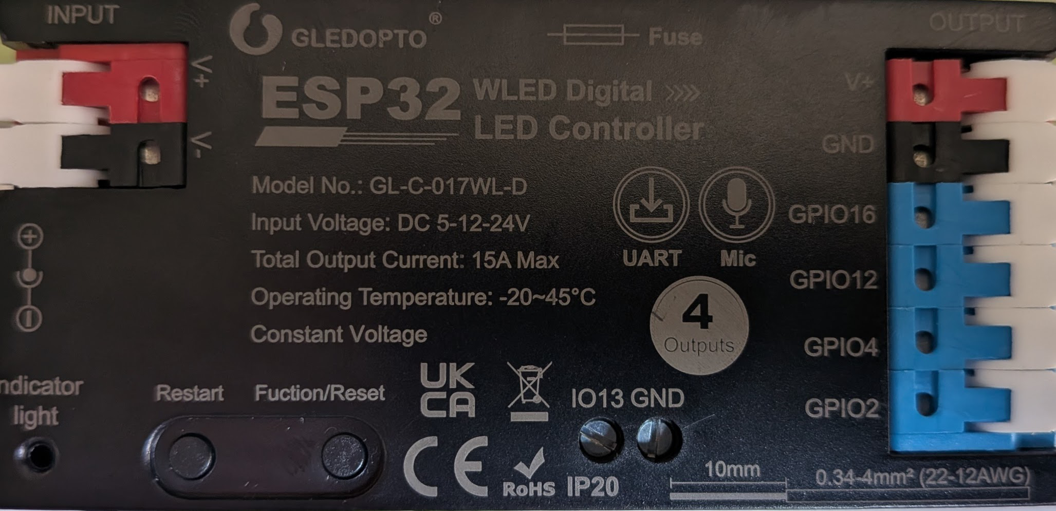
The ESP32 WLED Digital LED Controller (GL-C-017WL-D), manufactured by Gledopto, is a versatile microcontroller board designed for controlling LED strips and creating dynamic lighting effects. It integrates Wi-Fi and Bluetooth capabilities, making it ideal for smart lighting applications. Preloaded with the WLED firmware, this controller allows users to customize lighting patterns and remotely control LED strips via a web interface, mobile app, or smart home systems.
Explore Projects Built with ESP32 WLED Digital LED Controller

Explore Projects Built with ESP32 WLED Digital LED Controller
Common Applications and Use Cases
- Smart home lighting systems
- Decorative lighting for events and holidays
- Ambient lighting for gaming setups or home theaters
- Commercial lighting displays
- IoT-based lighting automation
Technical Specifications
The following table outlines the key technical details of the ESP32 WLED Digital LED Controller:
| Parameter | Specification |
|---|---|
| Manufacturer | Gledopto |
| Part ID | GL-C-017WL-D |
| Microcontroller | ESP32 Dual-Core Processor |
| Connectivity | Wi-Fi 802.11 b/g/n, Bluetooth 4.2 |
| Input Voltage | 5V DC (via USB) or 5-24V DC (via VIN pin) |
| Power Consumption | ~0.5W (controller only) |
| LED Strip Compatibility | WS2812, WS2813, SK6812, APA102, etc. |
| GPIO Pins | 16 (configurable for LED data, sensors) |
| Flash Memory | 4MB (for firmware and effects storage) |
| Operating Temperature | -20°C to 60°C |
| Dimensions | 50mm x 25mm x 10mm |
Pin Configuration and Descriptions
The ESP32 WLED Digital LED Controller features multiple pins for connecting LED strips, sensors, and power. Below is the pinout description:
| Pin Name | Function | Description |
|---|---|---|
| VIN | Power Input | Accepts 5-24V DC for powering the board and LEDs. |
| GND | Ground | Common ground for power and peripherals. |
| GPIO2 | LED Data Output | Default pin for controlling WS2812/WS2813 LEDs. |
| GPIO4 | Optional LED Data Output | Configurable for additional LED strips. |
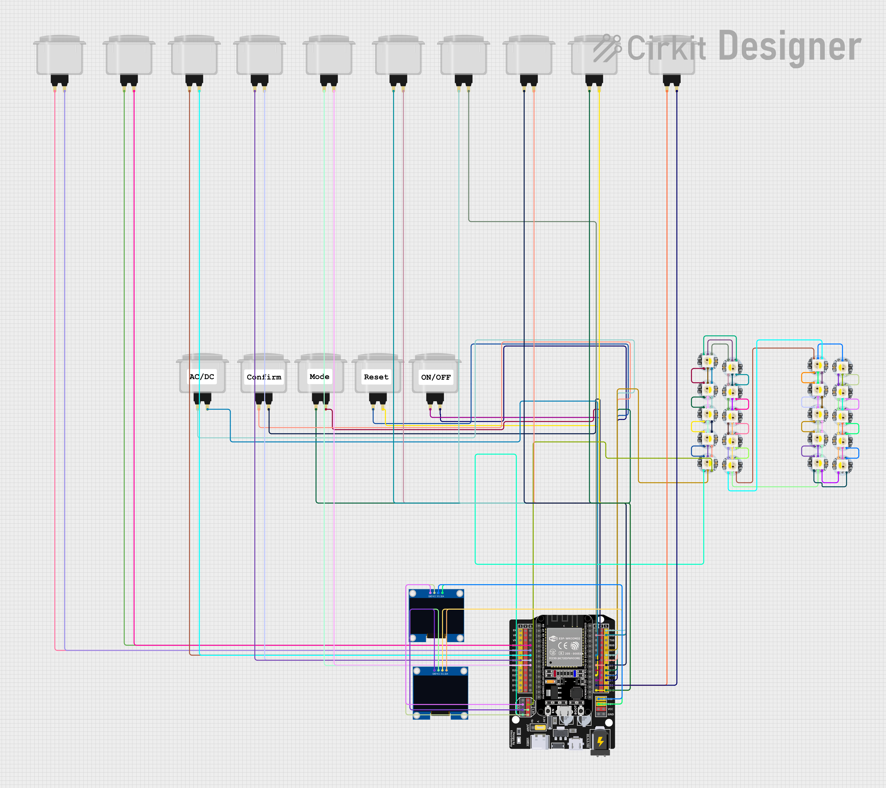
| GPIO16 | Button Input | For connecting a physical button to control modes. |
| GPIO12 | Analog Input | For connecting sensors (e.g., light or sound). |
| TX/RX | Serial Communication | For debugging or connecting external devices. |
| 3V3 | 3.3V Output | Power output for low-power peripherals. |
Usage Instructions
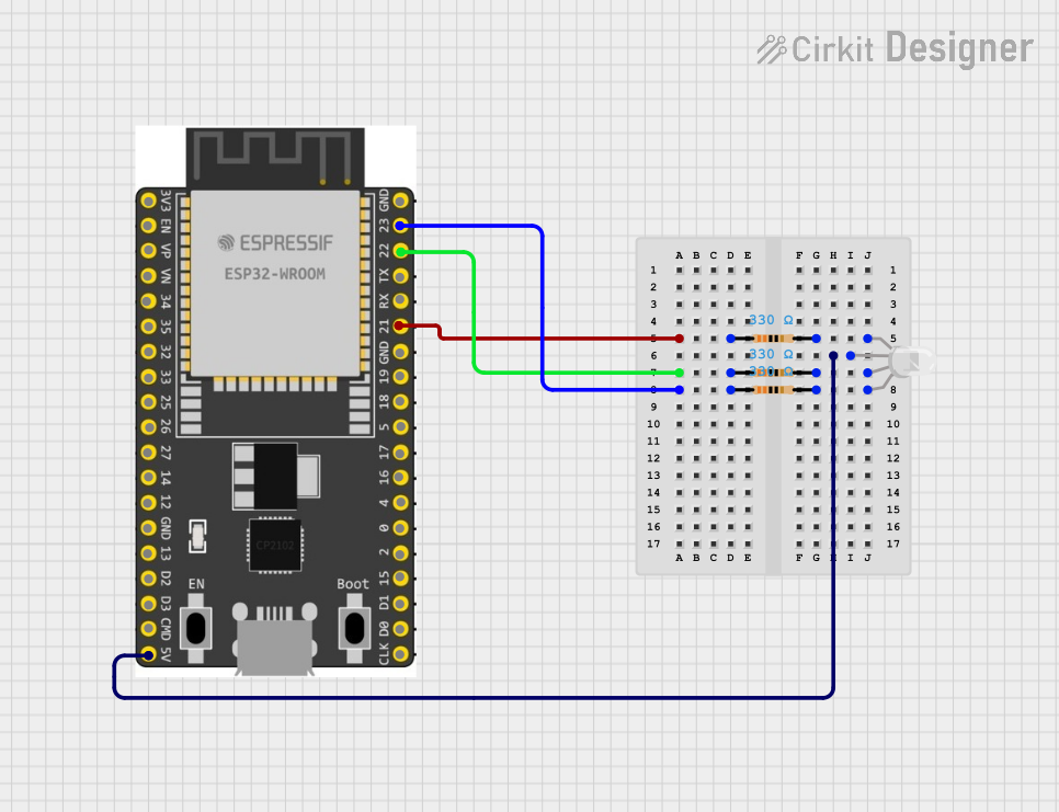
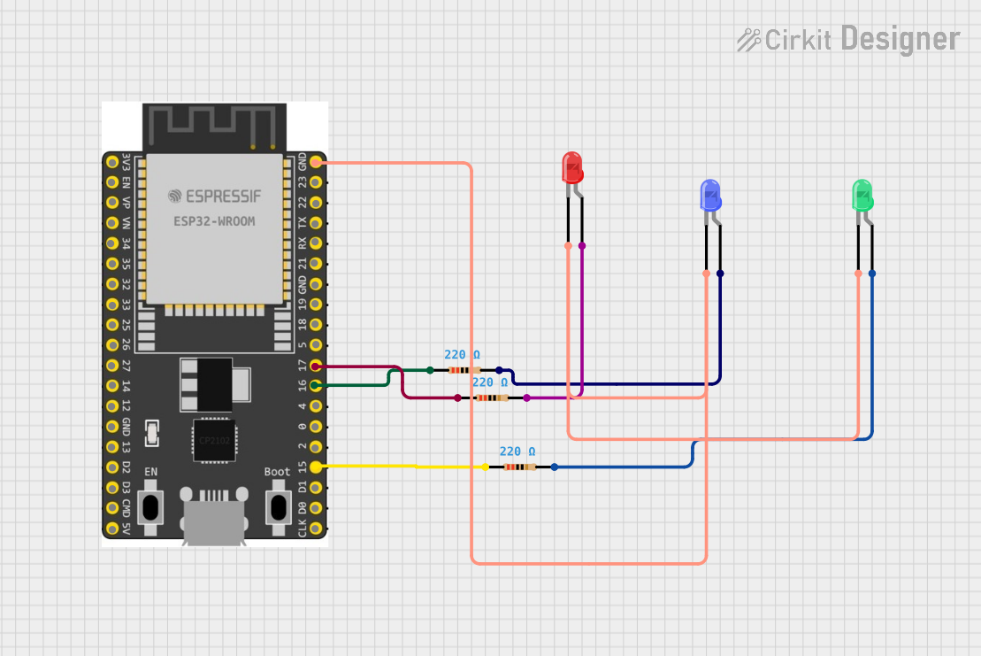
How to Use the Component in a Circuit
Powering the Controller:
- Connect a 5V DC power supply to the USB port or VIN pin.
- Ensure the power supply can handle the current requirements of the connected LED strip.
Connecting LED Strips:
- Connect the LED strip's data input to GPIO2 (default data pin).
- Connect the LED strip's power and ground to the VIN and GND pins, respectively.
Flashing or Updating Firmware:
- The controller comes preloaded with WLED firmware. To update:
- Connect the ESP32 to a computer via USB.
- Use the WLED web installer or a flashing tool like ESPHome-Flasher.
- The controller comes preloaded with WLED firmware. To update:
Accessing the WLED Interface:
- Power on the controller and connect to its Wi-Fi network (SSID:
WLED-AP). - Open a web browser and navigate to
http://4.3.2.1to access the WLED control panel. - Configure the controller to connect to your home Wi-Fi network for remote access.
- Power on the controller and connect to its Wi-Fi network (SSID:
Customizing Lighting Effects:
- Use the WLED web interface or mobile app to select and customize lighting effects.
- Integrate with smart home systems like Alexa or Google Assistant for voice control.
Important Considerations and Best Practices
- Power Supply: Ensure the power supply voltage matches the LED strip's requirements. Overvoltage can damage the LEDs and controller.
- Heat Management: Avoid enclosing the controller in a small, unventilated space to prevent overheating.
- Data Line Length: Keep the data line between the controller and LED strip as short as possible to avoid signal degradation.
- Firmware Updates: Regularly check for WLED firmware updates to access new features and bug fixes.
Example Code for Arduino Integration
The ESP32 WLED controller is typically used with preloaded firmware, but it can also be programmed using the Arduino IDE. Below is an example of controlling an LED strip using the FastLED library:
#include <FastLED.h>

// Define the number of LEDs and the data pin
#define NUM_LEDS 30
#define DATA_PIN 2

// Create an array to hold the LED data
CRGB leds[NUM_LEDS];

void setup() {
  // Initialize the LED strip
  FastLED.addLeds<WS2812, DATA_PIN, GRB>(leds, NUM_LEDS);
  FastLED.clear(); // Clear all LEDs
  FastLED.show();  // Update the LED strip
}

void loop() {
  // Set all LEDs to red
  for (int i = 0; i < NUM_LEDS; i++) {
    leds[i] = CRGB::Red;
  }
  FastLED.show(); // Update the LED strip with the new color
  delay(1000);    // Wait for 1 second

  // Turn off all LEDs
  FastLED.clear();
  FastLED.show();
  delay(1000);    // Wait for 1 second
}
Troubleshooting and FAQs
Common Issues and Solutions
LEDs Not Lighting Up:
- Verify the power supply is connected and providing the correct voltage.
- Check the data connection between the controller and LED strip.
- Ensure the LED strip is compatible with the WLED firmware (e.g., WS2812).
Controller Not Connecting to Wi-Fi:
- Ensure the Wi-Fi credentials are entered correctly in the WLED interface.
- Check for interference or weak Wi-Fi signal strength.
Flickering LEDs:
- Use a capacitor (e.g., 1000µF) across the power and ground lines to stabilize voltage.
- Add a resistor (e.g., 330Ω) in series with the data line to reduce noise.
Overheating:
- Ensure adequate ventilation around the controller.
- Avoid exceeding the maximum current rating of the power supply.
FAQs
Q: Can I control multiple LED strips with one controller?
A: Yes, you can configure additional GPIO pins (e.g., GPIO4) for controlling multiple LED strips.
Q: Is the controller compatible with RGBW LED strips?
A: Yes, the WLED firmware supports RGBW LED strips like SK6812.
Q: How do I reset the controller to factory settings?
A: Hold the physical button connected to GPIO16 for 10 seconds to reset the controller.
Q: Can I use the controller without Wi-Fi?
A: Yes, the controller can operate in standalone mode using the default WLED-AP network.