How to Use Actuator Motor: Examples, Pinouts, and Specs
Introduction
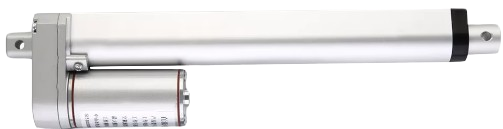
An Actuator Motor is an electromechanical device designed to convert electrical energy into mechanical motion. This type of motor is widely used in applications that require precise control of movement, such as in robotics, automation systems, valve control, and positioning systems. Actuator Motors can be found in both linear and rotary forms, depending on the type of motion they provide.
Explore Projects Built with Actuator Motor
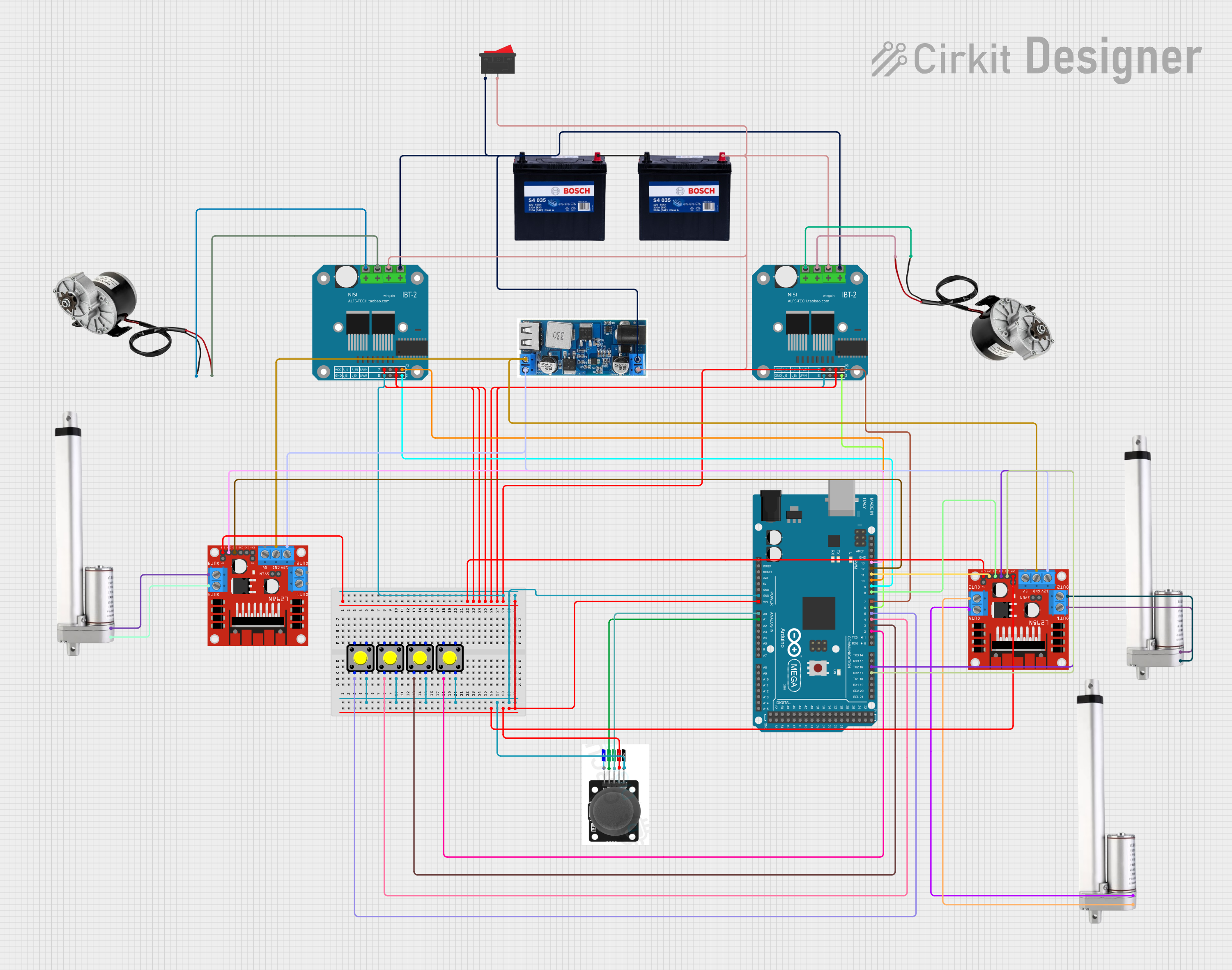
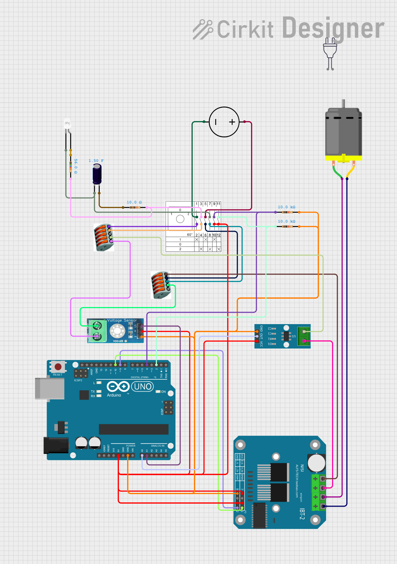
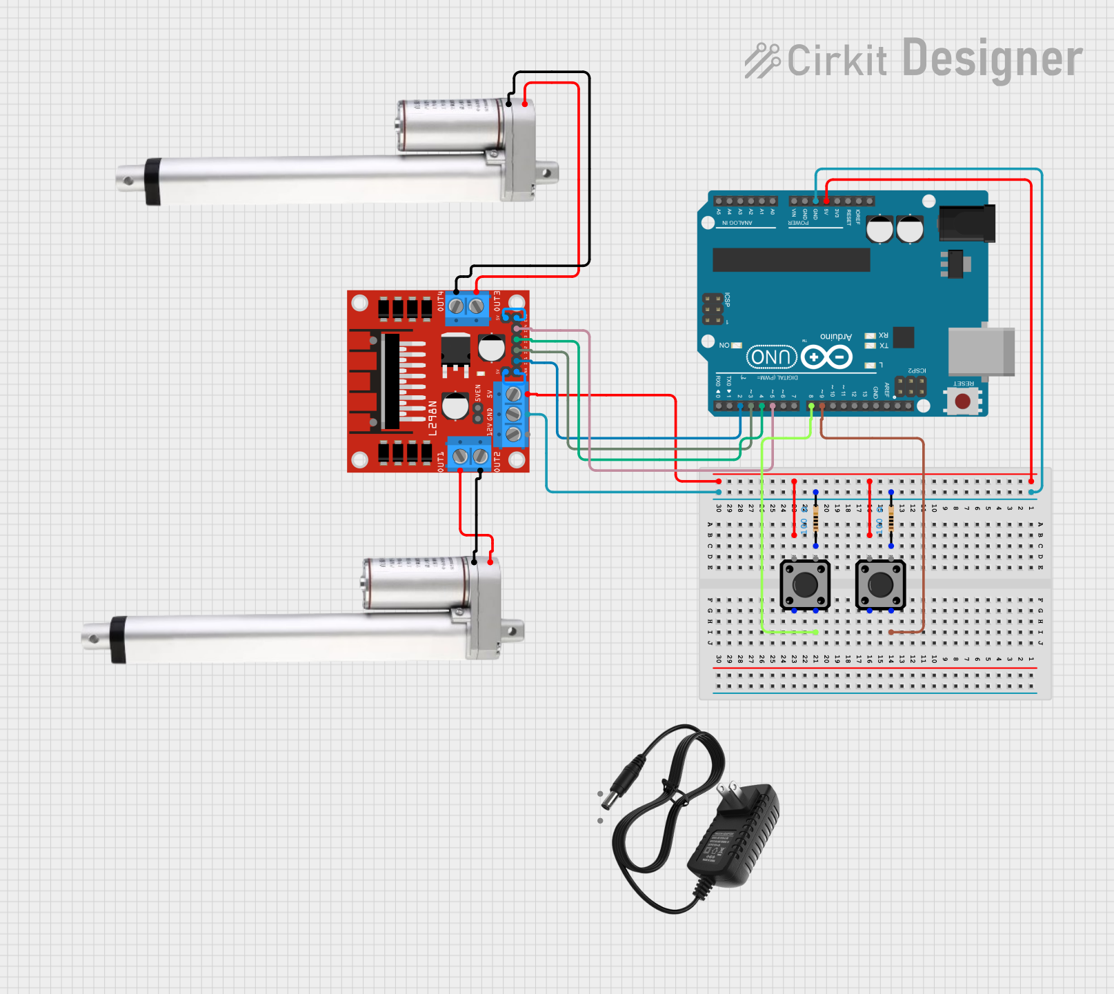

Explore Projects Built with Actuator Motor
Technical Specifications
Key Technical Details
- Voltage Range: Typically from 12V to 48V DC
- Current Consumption: Varies with load and model, often from 500mA to several Amperes
- Power Ratings: Depending on the size and application, can range from a few watts to several kilowatts
- Torque: Specified in Newton-meters (Nm) or ounce-inches (oz-in), depending on the model
- Speed: Given in revolutions per minute (RPM) for rotary actuators or millimeters per second (mm/s) for linear actuators
- Duty Cycle: Percentage of time the actuator can be operated continuously without overheating
Pin Configuration and Descriptions
| Pin Number | Description | Notes |
|---|---|---|
| 1 | V+ (Power Supply) | Connect to positive voltage supply |
| 2 | GND (Ground) | Connect to system ground |
| 3 | Control Signal Input | PWM, analog voltage, or digital signal |
| 4 | Feedback Output | Position or speed feedback (if available) |
| 5 | Enable | Active high or low to enable motor |
Note: The actual pin configuration may vary depending on the actuator model and manufacturer.
Usage Instructions
Integrating the Actuator Motor into a Circuit
- Power Supply Connection: Connect the V+ and GND pins to a suitable power supply, ensuring it matches the voltage and current requirements of the actuator motor.
- Control Signal: Apply the control signal to the Control Signal Input pin. This could be a PWM signal for speed control or a digital signal for direction control.
- Feedback Utilization: If the actuator motor provides feedback, connect the Feedback Output pin to an appropriate input on your control system to monitor the position or speed of the actuator.
- Enable Pin: Use the Enable pin to turn the actuator on or off. This can be connected to a microcontroller or switch.
Important Considerations and Best Practices
- Power Ratings: Do not exceed the voltage and current ratings of the actuator motor to prevent damage.
- Heat Dissipation: Ensure adequate cooling for the motor, especially during high-duty cycles or heavy loads.
- Control Signal: Match the control signal specifications (voltage level, frequency, etc.) with the actuator's requirements.
- Mounting: Securely mount the actuator to prevent movement that could lead to mechanical failure or imprecise operation.
Example Code for Arduino UNO
#include <Servo.h>

Servo actuatorMotor;  // Create a servo object to control the actuator motor

void setup() {
  actuatorMotor.attach(9);  // Attaches the actuator motor on pin 9 to the servo object
}

void loop() {
  actuatorMotor.write(90);  // Moves the actuator to the middle position
  delay(1000);              // Waits for 1 second
  actuatorMotor.write(0);   // Moves the actuator to the initial position
  delay(1000);              // Waits for 1 second
  actuatorMotor.write(180); // Moves the actuator to the final position
  delay(1000);              // Waits for 1 second
}
Note: The above code assumes the actuator motor is compatible with the Servo library. Some actuators may require a different library or direct PWM control.
Troubleshooting and FAQs
Common Issues
- Actuator Motor Does Not Move: Check the power supply connections and ensure the control signal is being sent correctly.
- Overheating: Reduce the duty cycle, improve cooling, or check for mechanical obstructions.
- Erratic Movement: Verify the control signal is stable and within the specified range.
Solutions and Tips
- Power Supply Issues: Use a regulated power supply to prevent voltage spikes that could damage the motor.
- Signal Interference: Keep control signal wires away from high-power lines to minimize electrical noise.
- Regular Maintenance: Periodically check for wear and tear, especially in mechanical linkages and connections.
FAQs
Q: Can I control the speed of the actuator motor? A: Yes, speed control is typically achieved through PWM signals.
Q: What is the lifespan of an actuator motor? A: Lifespan varies based on usage, load, and environmental conditions. Refer to the manufacturer's specifications for rated life expectancy.
Q: How do I reverse the direction of a rotary actuator motor? A: Reversing the polarity of the control signal or using an H-bridge circuit can reverse the motor's direction.
Q: Can I use an actuator motor outdoors? A: Ensure the actuator is rated for outdoor use or adequately protected from the elements.
For further assistance, consult the manufacturer's datasheet and technical support resources.