How to Use PIC18F57Q43 CURIOSITY NANO EVALUATION KIT: Examples, Pinouts, and Specs
Introduction
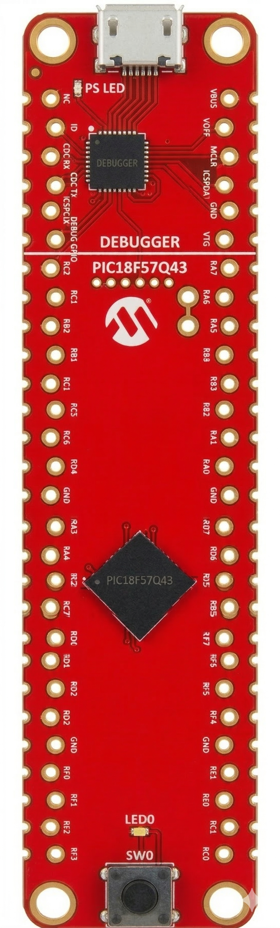
The PIC18F57Q43 Curiosity Nano Evaluation Kit is a compact development board designed by Microchip to evaluate the capabilities of the PIC18F57Q43 microcontroller. This board is ideal for rapid prototyping and testing applications, offering a wide range of peripherals and interfaces. It is USB-powered and integrates seamlessly with Microchip's development tools, such as MPLAB X IDE and MPLAB Code Configurator (MCC).
Explore Projects Built with PIC18F57Q43 CURIOSITY NANO EVALUATION KIT
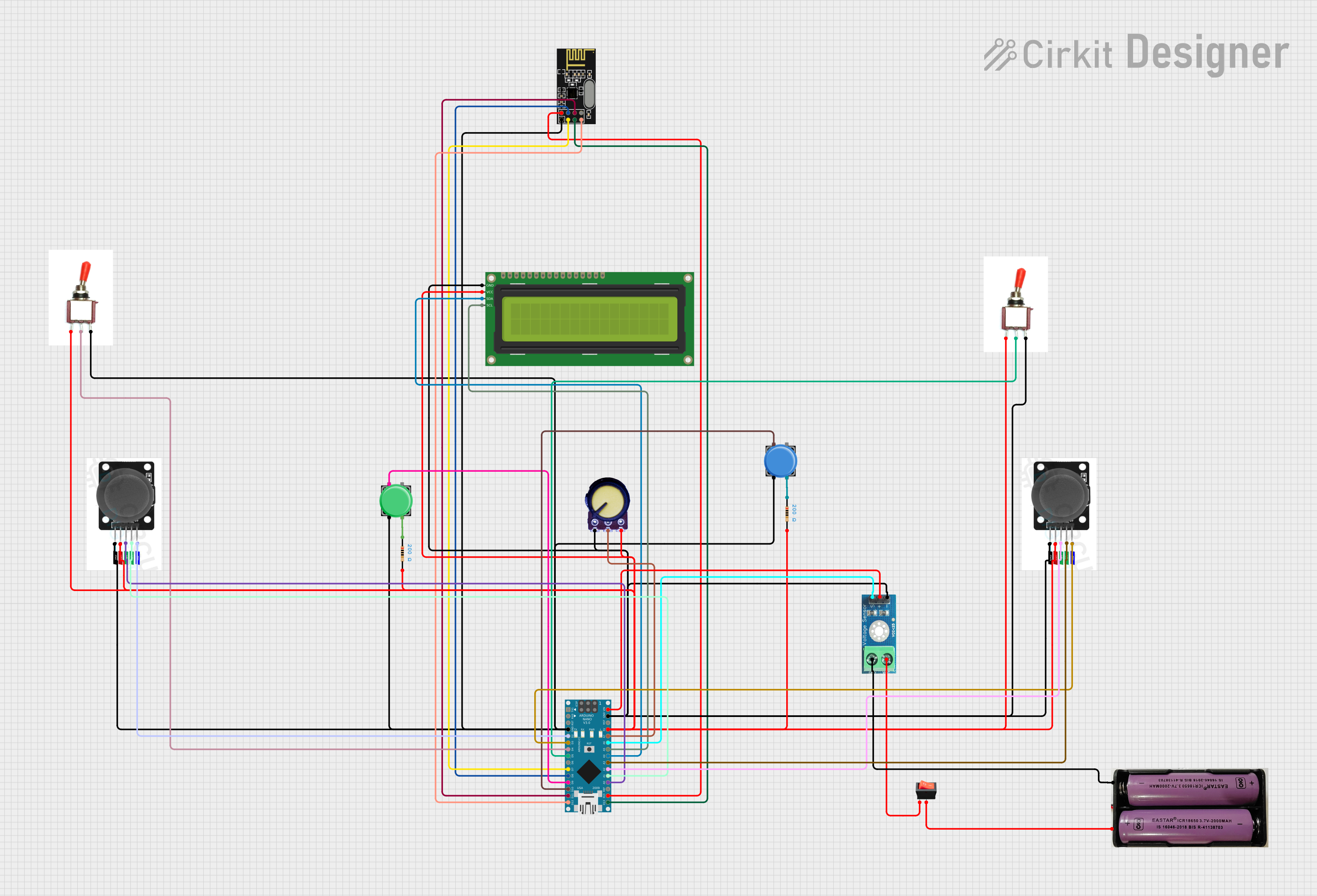
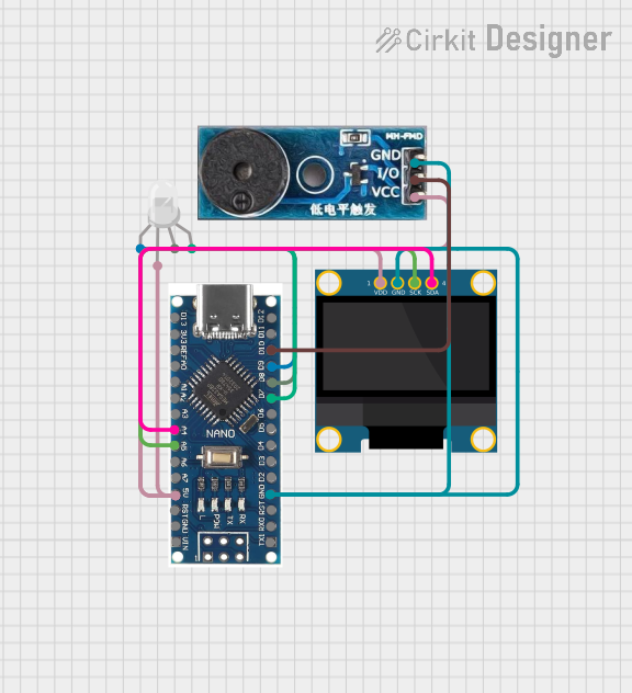
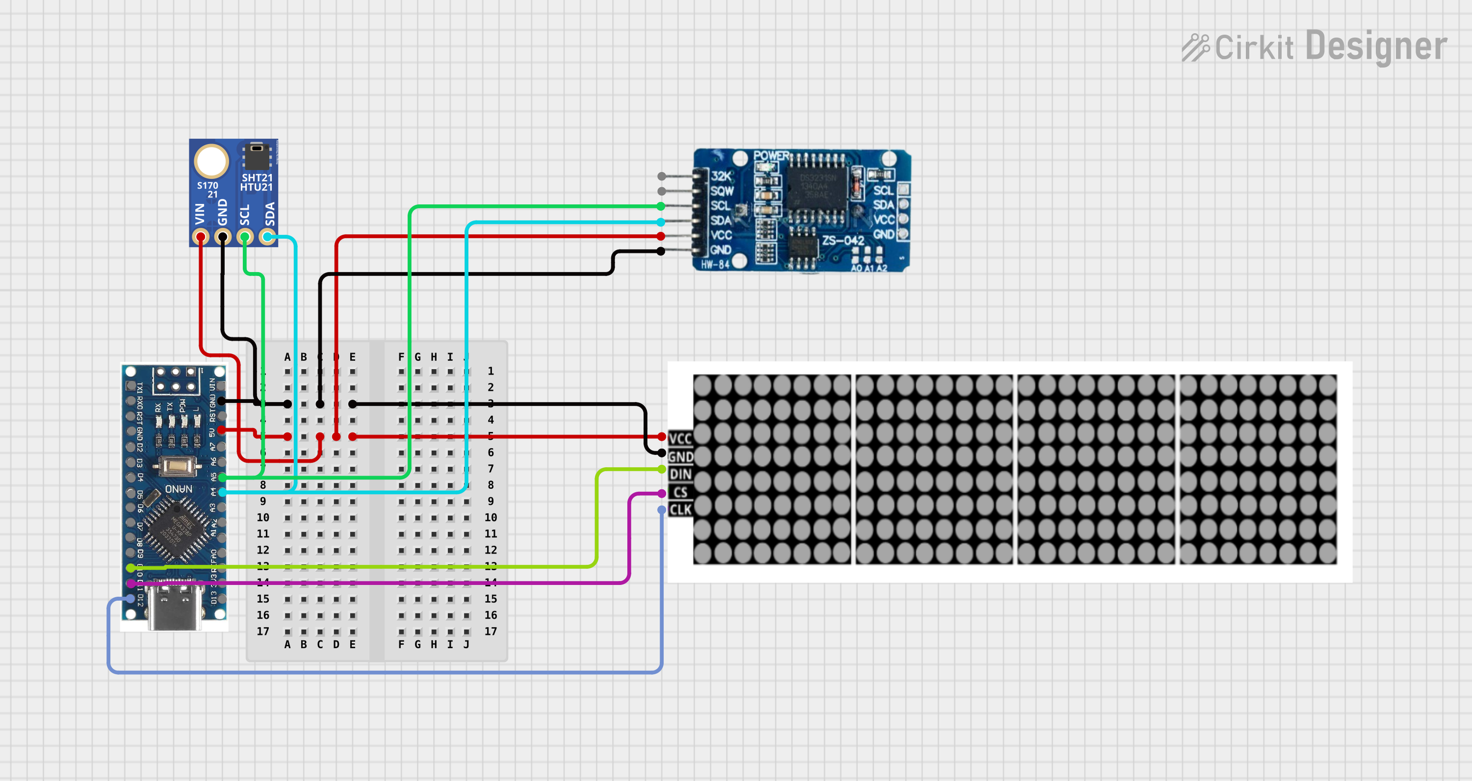
Explore Projects Built with PIC18F57Q43 CURIOSITY NANO EVALUATION KIT
Common Applications and Use Cases
- Embedded system prototyping
- IoT device development
- Sensor interfacing and data acquisition
- Motor control and automation
- Educational and research projects
Technical Specifications
Key Technical Details
| Parameter | Specification |
|---|---|
| Microcontroller | PIC18F57Q43 |
| Operating Voltage | 3.3V (regulated from USB) |
| Input Voltage Range | 5V (via USB) |
| Clock Speed | Up to 64 MHz (16 MIPS) |
| Flash Memory | 128 KB |
| SRAM | 4 KB |
| EEPROM | 256 Bytes |
| Communication Interfaces | UART, SPI, I2C, LIN, DMX, DALI, USB |
| GPIO Pins | 42 (multiplexed with peripherals) |
| ADC | 12-bit, up to 35 channels |
| DAC | 5-bit |
| PWM Channels | 10 |
| Debugging Interface | On-board debugger (DAP over USB) |
| Dimensions | 20 x 50 mm |
Pin Configuration and Descriptions
The PIC18F57Q43 Curiosity Nano Evaluation Kit features a 40-pin edge connector. Below is a summary of the key pins:
| Pin Number | Pin Name | Description |
|---|---|---|
| 1 | VCC | 3.3V power supply output |
| 2 | GND | Ground connection |
| 3 | RA0/AN0 | GPIO/Analog input channel 0 |
| 4 | RA1/AN1 | GPIO/Analog input channel 1 |
| 5 | RB0/INT0 | GPIO/External interrupt 0 |
| 6 | RC6/TX | UART Transmit |
| 7 | RC7/RX | UART Receive |
| 8 | SCL | I2C Clock Line |
| 9 | SDA | I2C Data Line |
| 10 | MISO | SPI Master-In-Slave-Out |
| 11 | MOSI | SPI Master-Out-Slave-In |
| 12 | SCK | SPI Clock Line |
| 13 | RESET | Reset pin |
| 14 | USB D+ | USB Data Positive |
| 15 | USB D- | USB Data Negative |
For a complete pinout, refer to the official Microchip documentation.
Usage Instructions
How to Use the Component in a Circuit
Powering the Board:
- Connect the board to a computer or USB power source using a micro-USB cable. The on-board debugger will power the board and provide 3.3V to the microcontroller.
Programming the Microcontroller:
- Use MPLAB X IDE with the MPLAB Code Configurator (MCC) to write and compile your code.
- The on-board debugger allows direct programming and debugging via USB.
Connecting Peripherals:
- Use the GPIO pins to interface with external components such as sensors, actuators, or displays.
- Configure the pins in software using MCC to set their mode (input/output/analog).
Communication Interfaces:
- Utilize UART, SPI, or I2C for communication with other devices. For example, connect an I2C sensor to the SCL and SDA pins.
Debugging:
- The on-board debugger supports DAP (Data Access Port) for real-time debugging. Use MPLAB X IDE to set breakpoints and monitor variables.
Important Considerations and Best Practices
- Voltage Levels: Ensure that external components connected to the GPIO pins operate at 3.3V logic levels to avoid damage.
- Pin Multiplexing: Many pins are multiplexed with multiple functions. Configure the pins carefully in software to avoid conflicts.
- Static Protection: Handle the board with care to prevent damage from electrostatic discharge (ESD).
- Firmware Updates: Keep the on-board debugger firmware up to date using Microchip's firmware updater tool.
Example Code for Arduino UNO Integration
Although the PIC18F57Q43 is not directly compatible with Arduino, you can use it to communicate with an Arduino UNO via UART. Below is an example of how to send data from the PIC18F57Q43 to an Arduino UNO:
PIC18F57Q43 Code (MPLAB X IDE):
#include <xc.h>

// Configuration bits (set according to your project requirements)
#pragma config FOSC = INTOSC    // Internal oscillator
#pragma config WDTE = OFF      // Watchdog Timer disabled

void UART_Init(void) {
    // Initialize UART with 9600 baud rate
    TX1STAbits.BRGH = 1;       // High-speed mode
    SP1BRGL = 207;             // Baud rate = 9600 (Fosc = 16 MHz)
    SP1BRGH = 0;
    RC1STAbits.SPEN = 1;       // Enable serial port
    TX1STAbits.TXEN = 1;       // Enable transmitter
}

void UART_SendChar(char c) {
    while (!TX1STAbits.TRMT);  // Wait until transmit buffer is empty
    TX1REG = c;                // Transmit character
}

void main(void) {
    UART_Init();
    while (1) {
        UART_SendChar('H');    // Send 'H' to Arduino
        __delay_ms(1000);      // Delay 1 second
    }
}
Arduino UNO Code:
void setup() {
  Serial.begin(9600); // Initialize UART with 9600 baud rate
}

void loop() {
  if (Serial.available() > 0) {
    char received = Serial.read(); // Read data from PIC18F57Q43
    Serial.print("Received: ");
    Serial.println(received);      // Print received data to Serial Monitor
  }
}
Troubleshooting and FAQs
Common Issues and Solutions
Board Not Detected by MPLAB X IDE:
- Ensure the USB cable is properly connected and functional.
- Check that the correct device is selected in MPLAB X IDE.
- Update the on-board debugger firmware if necessary.
Microcontroller Not Responding:
- Verify that the code is correctly compiled and uploaded.
- Check the power supply and ensure the board is receiving 3.3V.
Communication Issues (UART/I2C/SPI):
- Double-check the pin connections and ensure the correct pins are configured in software.
- Verify that the baud rate or clock speed matches between devices.
GPIO Pins Not Working:
- Ensure the pins are configured correctly in MCC (input/output/analog).
- Check for any conflicting pin assignments.
FAQs
Q: Can I power the board externally?
A: Yes, you can power the board externally by providing 3.3V to the VCC pin. However, ensure the USB is disconnected to avoid conflicts.
Q: Is the board compatible with Arduino IDE?
A: No, the PIC18F57Q43 is not directly compatible with Arduino IDE. Use MPLAB X IDE for development.
Q: How do I update the debugger firmware?
A: Use Microchip's firmware updater tool, available in MPLAB X IDE, to update the on-board debugger firmware.
Q: Can I use the board for low-power applications?
A: Yes, the PIC18F57Q43 supports low-power modes. Configure the microcontroller in software to reduce power consumption.