How to Use XLR female: Examples, Pinouts, and Specs
Introduction
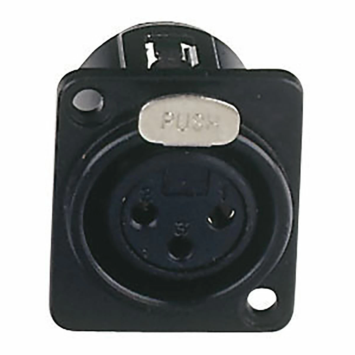
The XLR female connector, also known as a Cannon connector, is a standard in professional audio applications for transmitting balanced audio signals. It is characterized by its robust circular design and typically has three pins, although versions with more pins are available for different applications. XLR connectors are favored for their ability to provide a secure and noise-resistant connection, making them ideal for use with microphones, mixers, audio interfaces, speakers, and other professional audio equipment.
Explore Projects Built with XLR female


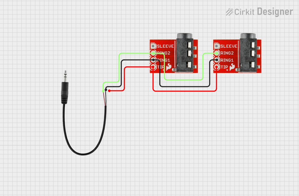
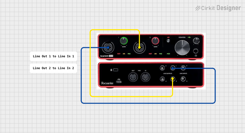
Explore Projects Built with XLR female
Technical Specifications
General Characteristics
- Type: Audio/Video Connector
- Gender: Female
- Number of Pins: 3 (standard for audio)
- Orientation: Circular
- Contact Plating: Typically nickel or silver
- Rated Voltage: Typically 125V (varies by manufacturer)
- Rated Current: Typically 15A (varies by manufacturer)
Pin Configuration and Descriptions
| Pin Number | Signal Type | Description |
|---|---|---|
| 1 | Ground | Shield and ground reference for audio signal |
| 2 | Hot | Positive phase of audio signal (also known as in-phase) |
| 3 | Cold | Negative phase of audio signal (also known as anti-phase) |
Usage Instructions
Integration into Audio Circuits
To use an XLR female connector in an audio circuit:
- Identify the Pins: Locate the pins on the connector. Pin 1 is typically connected to the connector's chassis and serves as the ground. Pins 2 and 3 are for the audio signal.
- Soldering Wires: Solder appropriate audio cables to the pins. Use balanced audio cable with two conductors and a shield.
- Cable Strain Relief: Ensure that the cable is secured with strain relief to prevent tension on the soldered connections.
- Testing: After soldering, test the connection with an audio source and receiving equipment to ensure signal integrity.
Best Practices
- Use high-quality connectors with durable plating to ensure a reliable connection and to minimize noise.
- Ensure that the cable and connector are compatible in terms of impedance to maintain signal quality.
- Avoid running audio cables parallel to power cables to prevent electromagnetic interference.
- Use a cable tester to check for continuity and correct wiring before connecting to audio equipment.
Troubleshooting and FAQs
Common Issues
- No Signal: Check the soldered connections for cold joints or shorts. Ensure that the cable is properly connected to the corresponding male XLR connector.
- Intermittent Signal: Inspect the cable for damage or breaks. Check the strain relief to ensure the cable is not pulling on the soldered joints.
- Noise in Audio: Ensure that the cable is fully shielded and that the shield is properly connected to Pin 1. Check for potential ground loops.
FAQs
Q: Can I use an XLR connector for mono audio signals? A: Yes, XLR connectors can be used for mono signals. Typically, Pin 2 would carry the signal and Pins 1 and 3 would be connected to ground.
Q: What is the difference between 3-pin and 5-pin XLR connectors? A: 3-pin XLR connectors are standard for balanced audio signals, while 5-pin versions are often used for lighting control (DMX) or stereo audio signals.
Q: How do I clean an XLR connector? A: Use a soft cloth and contact cleaner. Avoid spraying directly into the connector; instead, spray onto the cloth and gently wipe the pins.
Q: Can XLR connectors be used for high-power applications? A: XLR connectors are not typically designed for high-power connections. They are intended for low-voltage audio signals.
For any further assistance or detailed queries, it is recommended to consult the manufacturer's datasheet or contact technical support.
Please note that this documentation is a general guide and may not account for all variations and specific models of XLR female connectors. Always refer to the manufacturer's specifications for precise information.