How to Use RejsaCAN_OBD: Examples, Pinouts, and Specs
Introduction
The RejsaCAN_OBD is a diagnostic interface designed for vehicles that utilize the CAN (Controller Area Network) protocol. It enables communication with the onboard computer systems, allowing users to read diagnostic trouble codes (DTCs), monitor real-time data, and analyze vehicle performance. This component is ideal for automotive diagnostics, performance tuning, and real-time data logging.
Explore Projects Built with RejsaCAN_OBD


Explore Projects Built with RejsaCAN_OBD
Common Applications and Use Cases
- Reading and clearing diagnostic trouble codes (DTCs)
- Monitoring real-time vehicle data (e.g., engine RPM, speed, temperature)
- Performance tuning and optimization
- Data logging for research and development
- Integration with microcontrollers (e.g., Arduino) for custom automotive projects
Technical Specifications
The RejsaCAN_OBD is designed to interface with the OBD-II port of vehicles and supports the CAN protocol. Below are the key technical details:
General Specifications
| Parameter | Value |
|---|---|
| Protocol Support | CAN (ISO 11898) |
| Operating Voltage | 5V (via microcontroller) |
| Communication Interface | UART (Serial) |
| Baud Rate | Configurable (default: 500 kbps) |
| Operating Temperature | -40°C to +85°C |
| Dimensions | 50mm x 25mm x 10mm |
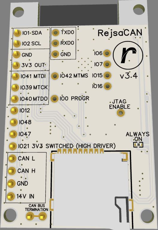
Pin Configuration and Descriptions
| Pin Name | Pin Number | Description |
|---|---|---|
| VCC | 1 | Power input (5V) |
| GND | 2 | Ground connection |
| RX | 3 | UART receive pin (connect to TX of microcontroller) |
| TX | 4 | UART transmit pin (connect to RX of microcontroller) |
| CAN_H | 5 | CAN high signal (connect to vehicle OBD-II port) |
| CAN_L | 6 | CAN low signal (connect to vehicle OBD-II port) |
Usage Instructions
How to Use the RejsaCAN_OBD in a Circuit
- Power the Module: Connect the
VCCpin to a 5V power source and theGNDpin to ground. - Connect to Microcontroller:
- Connect the
RXpin of the RejsaCAN_OBD to theTXpin of your microcontroller. - Connect the
TXpin of the RejsaCAN_OBD to theRXpin of your microcontroller.
- Connect the
- Connect to Vehicle OBD-II Port:
- Connect the
CAN_Hpin to the CAN high line of the vehicle's OBD-II port. - Connect the
CAN_Lpin to the CAN low line of the vehicle's OBD-II port.
- Connect the
- Configure Communication: Set the baud rate of your microcontroller's UART to match the RejsaCAN_OBD's default baud rate (500 kbps, unless reconfigured).
- Send and Receive Data: Use serial commands to send requests and receive data from the vehicle's onboard systems.
Important Considerations and Best Practices
- Ensure the vehicle's ignition is turned on before attempting to communicate with the OBD-II system.
- Use proper termination resistors (typically 120 ohms) on the CAN bus if required by your setup.
- Avoid connecting the module to vehicles that do not support the CAN protocol.
- Double-check all connections to prevent damage to the module or the vehicle's electronics.
Example Code for Arduino UNO
Below is an example of how to use the RejsaCAN_OBD with an Arduino UNO to read data from a vehicle:
#include <SoftwareSerial.h>

// Define RX and TX pins for SoftwareSerial
SoftwareSerial RejsaCAN(10, 11); // RX = pin 10, TX = pin 11

void setup() {
  Serial.begin(9600); // Initialize Serial Monitor
  RejsaCAN.begin(500000); // Initialize RejsaCAN_OBD at 500 kbps

  Serial.println("RejsaCAN_OBD Initialized");
  delay(1000);
}

void loop() {
  // Send a request to the vehicle (e.g., engine RPM)
  RejsaCAN.println("010C"); // OBD-II PID for engine RPM

  // Wait for a response
  if (RejsaCAN.available()) {
    String response = "";
    while (RejsaCAN.available()) {
      char c = RejsaCAN.read();
      response += c;
    }
    Serial.println("Response: " + response);
  }

  delay(1000); // Wait 1 second before sending the next request
}
Notes on the Code
- Replace
010Cwith the appropriate OBD-II PID for the data you want to retrieve. - Ensure the
SoftwareSeriallibrary is installed and configured correctly. - Use the Serial Monitor to view the responses from the RejsaCAN_OBD.
Troubleshooting and FAQs
Common Issues and Solutions
No Response from the Module:
- Ensure the vehicle's ignition is turned on.
- Verify that the
CAN_HandCAN_Lconnections are correct. - Check the baud rate configuration of your microcontroller.
Incorrect or Garbled Data:
- Confirm that the UART baud rate matches the RejsaCAN_OBD's baud rate.
- Check for loose or faulty connections.
Module Not Powering On:
- Verify that the
VCCpin is receiving 5V. - Check the ground connection.
- Verify that the
Vehicle Not Responding:
- Ensure the vehicle supports the CAN protocol.
- Verify that the OBD-II port is functional.
FAQs
Q: Can the RejsaCAN_OBD be used with vehicles that do not support CAN?
A: No, the RejsaCAN_OBD is specifically designed for vehicles that utilize the CAN protocol.
Q: How do I know if my vehicle supports the CAN protocol?
A: Most vehicles manufactured after 2008 support the CAN protocol. Check your vehicle's manual or OBD-II port specifications for confirmation.
Q: Can I use the RejsaCAN_OBD with other microcontrollers besides Arduino?
A: Yes, the RejsaCAN_OBD can be used with any microcontroller that supports UART communication, such as ESP32, STM32, or Raspberry Pi.
Q: Is it safe to leave the module connected to the vehicle?
A: Yes, but it is recommended to disconnect the module when not in use to prevent unnecessary power drain.
Q: How do I clear diagnostic trouble codes (DTCs)?
A: Send the OBD-II command 04 to clear all stored DTCs. Ensure you understand the implications of clearing codes before proceeding.