Cirkit Designer
Your all-in-one circuit design IDE
Home /
Component Documentation
How to Use ESP32-S2-WROVER: Examples, Pinouts, and Specs
Introduction
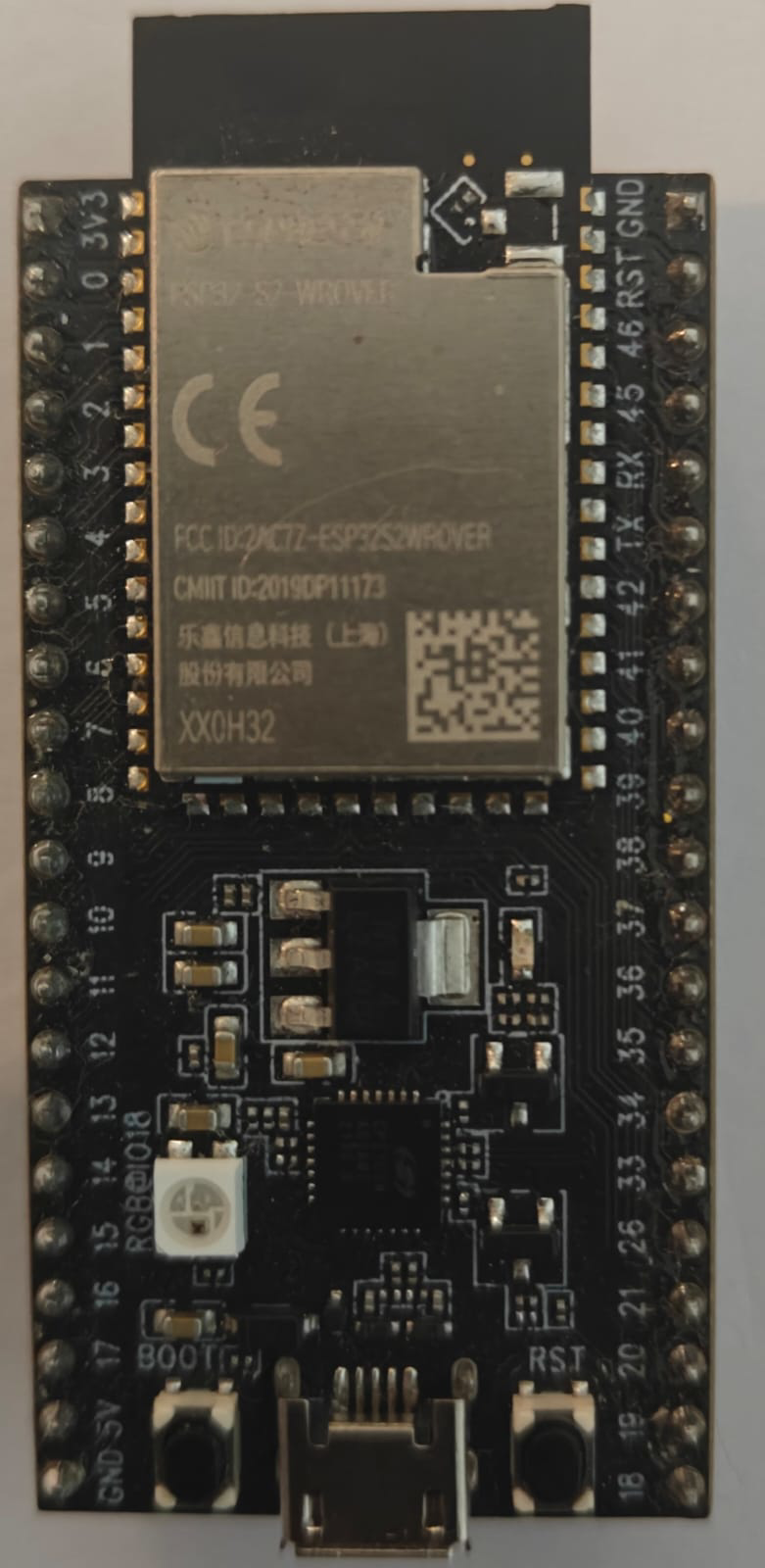
The ESP32-S2-WROVER is a powerful Wi-Fi microcontroller module developed by Espressif. It integrates a 2.4 GHz Wi-Fi transceiver, 320 KB of SRAM, and 2 MB of PSRAM, making it an ideal choice for IoT applications. This module offers high performance and low power consumption, making it suitable for a wide range of applications, including smart home devices, wearable electronics, and industrial automation.
Explore Projects Built with ESP32-S2-WROVER
ESP32-S2-WROVER and DS18B20 Temperature Monitoring System
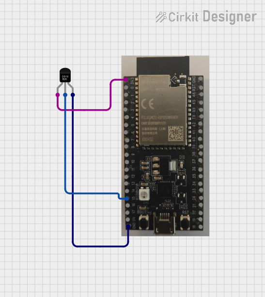
This circuit features an ESP32-S2-WROVER microcontroller connected to a DS18B20 temperature sensor. The ESP32-S2-WROVER reads temperature data from the DS18B20 sensor via GPIO 15 and prints the temperature readings to the Serial Monitor.
ESP32-S2-WROVER and GPS NEO 6M Based Real-Time GPS Tracker with Serial Monitor Output
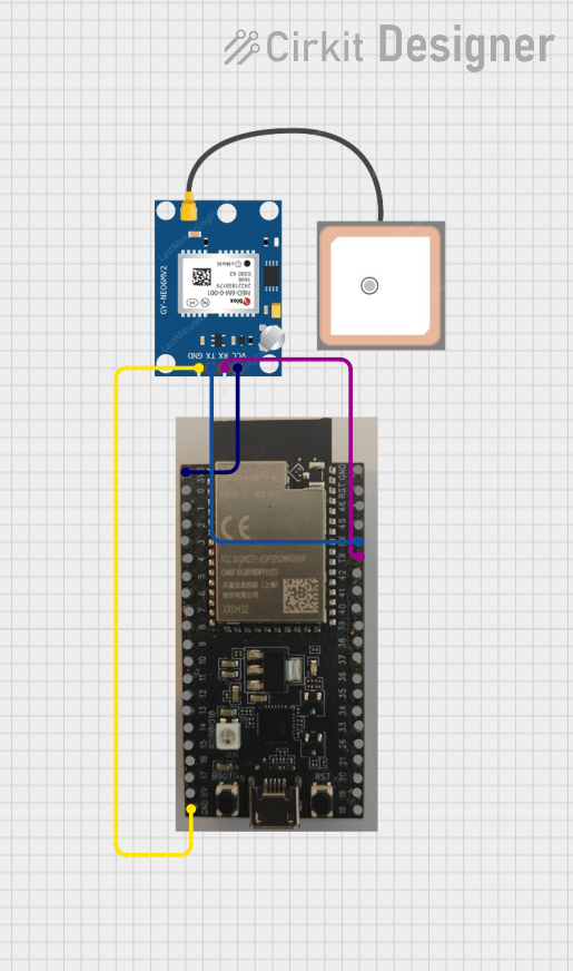
This circuit interfaces an ESP32-S2-WROVER microcontroller with a GPS NEO 6M module. The ESP32 reads GPS data from the NEO 6M via serial communication and prints the data to the Serial Monitor. Power and ground connections are provided from the ESP32 to the GPS module.
ESP32-Based GPS Tracker with SD Card Logging and Barometric Sensor

This circuit features an ESP32 Wroom Dev Kit as the main microcontroller, interfaced with an MPL3115A2 sensor for pressure and temperature readings, and a Neo 6M GPS module for location tracking. The ESP32 is also connected to an SD card reader for data logging purposes. A voltage regulator is used to step down the USB power supply to 3.3V, which powers the ESP32, the sensor, and the SD card reader.
ESP32-Based Multi-Sensor Health Monitoring System with Bluetooth Connectivity

This circuit features an ESP32-WROOM-32UE microcontroller as the central processing unit, interfacing with a variety of sensors and modules. It includes a MAX30100 pulse oximeter and heart-rate sensor, an MLX90614 infrared thermometer, an HC-05 Bluetooth module for wireless communication, and a Neo 6M GPS module for location tracking. All components are powered by a common voltage supply and are connected to specific GPIO pins on the ESP32 for data exchange, with the sensors using I2C communication and the modules using UART.
Explore Projects Built with ESP32-S2-WROVER
ESP32-S2-WROVER and DS18B20 Temperature Monitoring System
This circuit features an ESP32-S2-WROVER microcontroller connected to a DS18B20 temperature sensor. The ESP32-S2-WROVER reads temperature data from the DS18B20 sensor via GPIO 15 and prints the temperature readings to the Serial Monitor.
ESP32-S2-WROVER and GPS NEO 6M Based Real-Time GPS Tracker with Serial Monitor Output
This circuit interfaces an ESP32-S2-WROVER microcontroller with a GPS NEO 6M module. The ESP32 reads GPS data from the NEO 6M via serial communication and prints the data to the Serial Monitor. Power and ground connections are provided from the ESP32 to the GPS module.
ESP32-Based GPS Tracker with SD Card Logging and Barometric Sensor
This circuit features an ESP32 Wroom Dev Kit as the main microcontroller, interfaced with an MPL3115A2 sensor for pressure and temperature readings, and a Neo 6M GPS module for location tracking. The ESP32 is also connected to an SD card reader for data logging purposes. A voltage regulator is used to step down the USB power supply to 3.3V, which powers the ESP32, the sensor, and the SD card reader.
ESP32-Based Multi-Sensor Health Monitoring System with Bluetooth Connectivity
This circuit features an ESP32-WROOM-32UE microcontroller as the central processing unit, interfacing with a variety of sensors and modules. It includes a MAX30100 pulse oximeter and heart-rate sensor, an MLX90614 infrared thermometer, an HC-05 Bluetooth module for wireless communication, and a Neo 6M GPS module for location tracking. All components are powered by a common voltage supply and are connected to specific GPIO pins on the ESP32 for data exchange, with the sensors using I2C communication and the modules using UART.
Technical Specifications
Key Technical Details
| Parameter | Value |
|---|---|
| Wi-Fi Standard | 802.11 b/g/n |
| Operating Voltage | 3.0V to 3.6V |
| Flash Memory | 4 MB |
| SRAM | 320 KB |
| PSRAM | 2 MB |
| CPU | Xtensa® single-core 32-bit LX7 |
| Clock Speed | Up to 240 MHz |
| GPIO Pins | 43 |
| Operating Temperature | -40°C to +85°C |
Pin Configuration and Descriptions
| Pin Number | Pin Name | Description |
|---|---|---|
| 1 | VDD3P3 | 3.3V Power Supply |
| 2 | GND | Ground |
| 3 | GPIO0 | General Purpose I/O |
| 4 | GPIO1 | General Purpose I/O |
| 5 | GPIO2 | General Purpose I/O |
| 6 | GPIO3 | General Purpose I/O |
| 7 | GPIO4 | General Purpose I/O |
| 8 | GPIO5 | General Purpose I/O |
| 9 | GPIO6 | General Purpose I/O |
| 10 | GPIO7 | General Purpose I/O |
| 11 | GPIO8 | General Purpose I/O |
| 12 | GPIO9 | General Purpose I/O |
| 13 | GPIO10 | General Purpose I/O |
| 14 | GPIO11 | General Purpose I/O |
| 15 | GPIO12 | General Purpose I/O |
| 16 | GPIO13 | General Purpose I/O |
| 17 | GPIO14 | General Purpose I/O |
| 18 | GPIO15 | General Purpose I/O |
| 19 | GPIO16 | General Purpose I/O |
| 20 | GPIO17 | General Purpose I/O |
| 21 | GPIO18 | General Purpose I/O |
| 22 | GPIO19 | General Purpose I/O |
| 23 | GPIO20 | General Purpose I/O |
| 24 | GPIO21 | General Purpose I/O |
| 25 | GPIO22 | General Purpose I/O |
| 26 | GPIO23 | General Purpose I/O |
| 27 | GPIO24 | General Purpose I/O |
| 28 | GPIO25 | General Purpose I/O |
| 29 | GPIO26 | General Purpose I/O |
| 30 | GPIO27 | General Purpose I/O |
| 31 | GPIO28 | General Purpose I/O |
| 32 | GPIO29 | General Purpose I/O |
| 33 | GPIO30 | General Purpose I/O |
| 34 | GPIO31 | General Purpose I/O |
| 35 | GPIO32 | General Purpose I/O |
| 36 | GPIO33 | General Purpose I/O |
| 37 | GPIO34 | General Purpose I/O |
| 38 | GPIO35 | General Purpose I/O |
| 39 | GPIO36 | General Purpose I/O |
| 40 | GPIO37 | General Purpose I/O |
| 41 | GPIO38 | General Purpose I/O |
| 42 | GPIO39 | General Purpose I/O |
| 43 | GPIO40 | General Purpose I/O |
Usage Instructions
How to Use the Component in a Circuit
- Power Supply: Connect the VDD3P3 pin to a 3.3V power supply and the GND pin to ground.
- GPIO Pins: Use the GPIO pins for interfacing with other components such as sensors, actuators, and displays.
- Programming: The ESP32-S2-WROVER can be programmed using the Arduino IDE or Espressif's ESP-IDF.
Important Considerations and Best Practices
- Power Supply: Ensure a stable 3.3V power supply to avoid damage to the module.
- GPIO Voltage Levels: The GPIO pins are not 5V tolerant. Ensure that the voltage levels of connected devices are within the 3.3V range.
- Antenna Placement: For optimal Wi-Fi performance, place the module in a location with minimal obstructions and interference.
Example Code for Arduino UNO
#include <WiFi.h>

// Replace with your network credentials
const char* ssid = "your_SSID";
const char* password = "your_PASSWORD";

void setup() {
  Serial.begin(115200);

  // Connect to Wi-Fi
  WiFi.begin(ssid, password);

  // Wait for connection
  while (WiFi.status() != WL_CONNECTED) {
    delay(1000);
    Serial.println("Connecting to WiFi...");
  }

  Serial.println("Connected to WiFi");
}

void loop() {
  // Put your main code here, to run repeatedly
}
Troubleshooting and FAQs
Common Issues Users Might Face
- Wi-Fi Connection Issues: The module may have difficulty connecting to Wi-Fi networks with weak signals or high interference.
- Power Supply Problems: An unstable or insufficient power supply can cause the module to reset or malfunction.
- GPIO Pin Conflicts: Incorrectly configured GPIO pins can lead to unexpected behavior or damage to the module.
Solutions and Tips for Troubleshooting
- Wi-Fi Connection Issues: Ensure that the module is within range of the Wi-Fi router and that there are minimal obstructions. Check the SSID and password for accuracy.
- Power Supply Problems: Use a stable 3.3V power supply with sufficient current capacity. Avoid using long or thin wires for power connections.
- GPIO Pin Conflicts: Double-check the pin configuration and ensure that no two devices are trying to use the same GPIO pin simultaneously.
By following these guidelines and best practices, you can effectively utilize the ESP32-S2-WROVER module in your projects and applications.