How to Use 60x60x20 Fan 24V: Examples, Pinouts, and Specs
Introduction
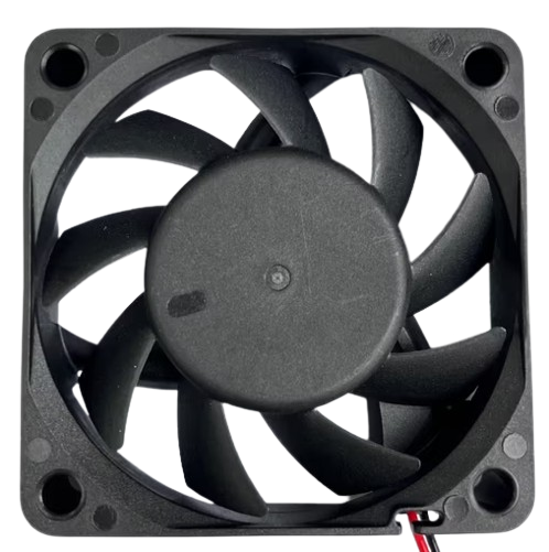
The 60x60x20 Fan 24V is a compact axial fan designed for efficient cooling in electronic and industrial applications. With its 60mm x 60mm x 20mm dimensions and 24V operating voltage, this fan is ideal for dissipating heat in confined spaces, ensuring optimal performance and longevity of electronic components. Its lightweight and durable design make it a popular choice for use in power supplies, 3D printers, computer systems, and other heat-sensitive devices.
Explore Projects Built with 60x60x20 Fan 24V


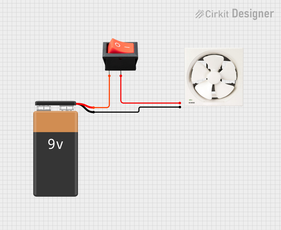
Explore Projects Built with 60x60x20 Fan 24V
Common Applications
- Cooling for power supplies and voltage regulators
- Heat dissipation in 3D printers and CNC machines
- Ventilation in computer cases and servers
- Thermal management in industrial control systems
- General-purpose cooling for small enclosures
Technical Specifications
Below are the key technical details of the 60x60x20 Fan 24V:
| Parameter | Specification |
|---|---|
| Dimensions | 60mm x 60mm x 20mm |
| Operating Voltage | 24V DC |
| Current Consumption | ~0.1A (varies by model) |
| Power Consumption | ~2.4W |
| Airflow | ~20-30 CFM (Cubic Feet per Minute) |
| Noise Level | ~25-35 dBA |
| Bearing Type | Sleeve or Ball Bearing |
| Connector Type | 2-pin or 3-pin (varies by model) |
| Operating Temperature | -10°C to +70°C |
| Weight | ~30g |
Pin Configuration
The fan typically comes with a 2-pin or 3-pin connector. Below is the pin configuration:
2-Pin Connector
| Pin Number | Wire Color | Description |
|---|---|---|
| 1 | Red | Positive (+24V DC) |
| 2 | Black | Ground (GND) |
3-Pin Connector
| Pin Number | Wire Color | Description |
|---|---|---|
| 1 | Red | Positive (+24V DC) |
| 2 | Black | Ground (GND) |
| 3 | Yellow | Tachometer Signal (optional) |
Usage Instructions
How to Use the Fan in a Circuit
- Power Supply: Ensure the fan is connected to a 24V DC power source. Verify that the power supply can provide sufficient current (at least 0.1A) for the fan's operation.
- Wiring:
- For a 2-pin fan, connect the red wire to the positive terminal of the power supply and the black wire to the ground terminal.
- For a 3-pin fan, connect the red and black wires as above. The yellow wire (if present) can be connected to a microcontroller or monitoring circuit to read the fan's speed (tachometer signal).
- Mounting: Secure the fan in place using screws or adhesive mounts. Ensure proper airflow direction by checking the fan's label or airflow arrow.
- Testing: Power on the circuit and verify that the fan spins smoothly and provides adequate airflow.
Important Considerations
- Polarity: Always connect the wires with the correct polarity to avoid damaging the fan.
- Voltage: Do not exceed the rated 24V DC operating voltage, as this may cause overheating or permanent damage.
- Airflow Direction: Ensure the fan is oriented correctly to direct airflow where needed. Most fans have an arrow indicating the airflow direction.
- Noise: If noise levels are critical, consider using a ball-bearing version of the fan for quieter operation.
- Tachometer Signal: If using the tachometer signal, ensure your microcontroller or monitoring circuit is compatible with the fan's output signal.
Example: Connecting to an Arduino UNO
If you want to monitor the fan's speed using the tachometer signal, you can connect the fan to an Arduino UNO. Below is an example code snippet:
// Example code to read the tachometer signal from a 60x60x20 Fan 24V
// Connect the fan's red wire to 24V, black wire to GND, and yellow wire to pin 2.

const int tachPin = 2;  // Pin connected to the fan's tachometer signal
volatile int fanPulseCount = 0;  // Variable to store pulse count

void setup() {
  pinMode(tachPin, INPUT_PULLUP);  // Set tachometer pin as input with pull-up
  attachInterrupt(digitalPinToInterrupt(tachPin), countFanPulses, FALLING);
  Serial.begin(9600);  // Initialize serial communication
}

void loop() {
  delay(1000);  // Wait for 1 second
  int rpm = (fanPulseCount / 2) * 60;  // Calculate RPM (2 pulses per revolution)
  Serial.print("Fan Speed: ");
  Serial.print(rpm);
  Serial.println(" RPM");
  fanPulseCount = 0;  // Reset pulse count for the next measurement
}

void countFanPulses() {
  fanPulseCount++;  // Increment pulse count on each falling edge
}
Notes:
- Ensure the Arduino is powered separately from the fan, as the fan requires 24V while the Arduino operates at 5V.
- Use a level shifter or voltage divider if the tachometer signal exceeds 5V.
Troubleshooting and FAQs
Common Issues and Solutions
Fan Does Not Spin:
- Cause: Incorrect wiring or insufficient power supply.
- Solution: Double-check the wiring and ensure the power supply provides 24V DC with sufficient current.
Excessive Noise:
- Cause: Dust accumulation, worn bearings, or improper mounting.
- Solution: Clean the fan blades, check for obstructions, and ensure the fan is securely mounted. Consider replacing the fan if the bearings are worn.
Low Airflow:
- Cause: Blocked airflow or incorrect orientation.
- Solution: Remove any obstructions and verify the fan's orientation using the airflow arrow.
Tachometer Signal Not Detected:
- Cause: Incorrect connection or incompatible microcontroller.
- Solution: Verify the yellow wire is connected to the correct pin and ensure the microcontroller can read the tachometer signal.
FAQs
Q: Can I use this fan with a 12V power supply?
A: No, the fan is designed for 24V DC operation. Using a lower voltage may result in insufficient airflow or failure to start.
Q: How do I clean the fan?
A: Use compressed air to remove dust from the blades and housing. Avoid using water or solvents, as they may damage the fan.
Q: Can I control the fan speed?
A: This fan does not have built-in speed control. However, you can use a PWM (Pulse Width Modulation) controller to adjust the voltage and control the speed.
Q: What is the lifespan of this fan?
A: The lifespan depends on the bearing type. Sleeve bearings typically last ~30,000 hours, while ball bearings can last ~50,000 hours or more under normal operating conditions.