Cirkit Designer Logo
Cirkit Designer
Your all-in-one circuit design IDE
Home / 
Component Documentation

How to Use LaskaKit TPS62A02 Step-down 4.0-5.5V 3.3V/2A: Examples, Pinouts, and Specs

Image of LaskaKit TPS62A02 Step-down 4.0-5.5V 3.3V/2A
Cirkit Designer LogoDesign with LaskaKit TPS62A02 Step-down 4.0-5.5V 3.3V/2A in Cirkit Designer

Introduction

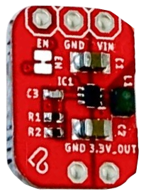
The LaskaKit TPS62A02 is a high-efficiency step-down (buck) voltage regulator designed to convert input voltages ranging from 4.0V to 5.5V into a stable 3.3V output. It is capable of delivering up to 2A of continuous current, making it ideal for powering low-voltage devices from higher-voltage sources. This compact and reliable regulator is widely used in applications such as microcontroller-based systems, IoT devices, portable electronics, and battery-powered projects.

Explore Projects Built with LaskaKit TPS62A02 Step-down 4.0-5.5V 3.3V/2A

Use Cirkit Designer to design, explore, and prototype these projects online. Some projects support real-time simulation. Click "Open Project" to start designing instantly!
Battery-Powered 18650 Li-ion Charger with USB Output and Adjustable Voltage Regulator
Image of Breadboard: A project utilizing LaskaKit TPS62A02 Step-down 4.0-5.5V 3.3V/2A in a practical application
This circuit is a battery management and power supply system that uses three 3.7V batteries connected to a 3S 10A Li-ion 18650 Charger Protection Board Module for balanced charging and protection. The system includes a TP4056 Battery Charging Protection Module for additional charging safety, a Step Up Boost Power Converter to regulate and boost the voltage, and a USB regulator to provide a stable 5V output, controlled by a push switch.
Cirkit Designer LogoOpen Project in Cirkit Designer
Battery-Powered Arduino UNO and ESP-8266 Smart Controller with LCD and RTC
Image of Ogie Diagram: A project utilizing LaskaKit TPS62A02 Step-down 4.0-5.5V 3.3V/2A in a practical application
This circuit is a power management and control system that uses a 12V power supply and a 18650 Li-ion battery pack to provide a stable 5V output through a step-down buck converter. It includes an Arduino UNO, an ESP-8266 controller, a DS1307 RTC module, and a 20x4 I2C LCD display for monitoring and control purposes. The ULN2003A breakout board is used for driving higher current loads.
Cirkit Designer LogoOpen Project in Cirkit Designer
Battery-Powered Adjustable Voltage Regulator with Li-ion 18650 Batteries and BMS
Image of mini ups: A project utilizing LaskaKit TPS62A02 Step-down 4.0-5.5V 3.3V/2A in a practical application
This circuit is a power management system that uses four Li-ion 18650 batteries connected to a 2S 30A BMS for battery management and protection. The system includes step-up and step-down voltage regulators to provide adjustable output voltages, controlled by a rocker switch, and multiple DC jacks for power input and output.
Cirkit Designer LogoOpen Project in Cirkit Designer
Battery-Powered DC Motor Control with USB Charging and LED Indicator
Image of lumantas: A project utilizing LaskaKit TPS62A02 Step-down 4.0-5.5V 3.3V/2A in a practical application
This circuit is designed to charge a Li-ion battery and power a DC motor and a 12V LED. The TP4056 module manages the battery charging process, while the PowerBoost 1000 and MT3608 boost converters step up the voltage to drive the motor and LED, respectively. Two rocker switches control the power flow to the LED and the charging circuit.
Cirkit Designer LogoOpen Project in Cirkit Designer

Explore Projects Built with LaskaKit TPS62A02 Step-down 4.0-5.5V 3.3V/2A

Use Cirkit Designer to design, explore, and prototype these projects online. Some projects support real-time simulation. Click "Open Project" to start designing instantly!
Image of Breadboard: A project utilizing LaskaKit TPS62A02 Step-down 4.0-5.5V 3.3V/2A in a practical application
Battery-Powered 18650 Li-ion Charger with USB Output and Adjustable Voltage Regulator
This circuit is a battery management and power supply system that uses three 3.7V batteries connected to a 3S 10A Li-ion 18650 Charger Protection Board Module for balanced charging and protection. The system includes a TP4056 Battery Charging Protection Module for additional charging safety, a Step Up Boost Power Converter to regulate and boost the voltage, and a USB regulator to provide a stable 5V output, controlled by a push switch.
Cirkit Designer LogoOpen Project in Cirkit Designer
Image of Ogie Diagram: A project utilizing LaskaKit TPS62A02 Step-down 4.0-5.5V 3.3V/2A in a practical application
Battery-Powered Arduino UNO and ESP-8266 Smart Controller with LCD and RTC
This circuit is a power management and control system that uses a 12V power supply and a 18650 Li-ion battery pack to provide a stable 5V output through a step-down buck converter. It includes an Arduino UNO, an ESP-8266 controller, a DS1307 RTC module, and a 20x4 I2C LCD display for monitoring and control purposes. The ULN2003A breakout board is used for driving higher current loads.
Cirkit Designer LogoOpen Project in Cirkit Designer
Image of mini ups: A project utilizing LaskaKit TPS62A02 Step-down 4.0-5.5V 3.3V/2A in a practical application
Battery-Powered Adjustable Voltage Regulator with Li-ion 18650 Batteries and BMS
This circuit is a power management system that uses four Li-ion 18650 batteries connected to a 2S 30A BMS for battery management and protection. The system includes step-up and step-down voltage regulators to provide adjustable output voltages, controlled by a rocker switch, and multiple DC jacks for power input and output.
Cirkit Designer LogoOpen Project in Cirkit Designer
Image of lumantas: A project utilizing LaskaKit TPS62A02 Step-down 4.0-5.5V 3.3V/2A in a practical application
Battery-Powered DC Motor Control with USB Charging and LED Indicator
This circuit is designed to charge a Li-ion battery and power a DC motor and a 12V LED. The TP4056 module manages the battery charging process, while the PowerBoost 1000 and MT3608 boost converters step up the voltage to drive the motor and LED, respectively. Two rocker switches control the power flow to the LED and the charging circuit.
Cirkit Designer LogoOpen Project in Cirkit Designer

Common Applications

  • Powering 3.3V microcontrollers (e.g., ESP32, Arduino boards with 3.3V logic)
  • Supplying stable voltage to sensors and modules
  • Battery-powered devices requiring efficient voltage conversion
  • IoT and wearable electronics

Technical Specifications

The following table outlines the key technical details of the LaskaKit TPS62A02:

Parameter Value
Input Voltage Range 4.0V to 5.5V
Output Voltage 3.3V (fixed)
Maximum Output Current 2A
Efficiency Up to 95%
Switching Frequency 2.25 MHz
Operating Temperature -40°C to +125°C
Package Type SOT-23-6

Pin Configuration and Descriptions

The TPS62A02 comes in a compact SOT-23-6 package with the following pinout:

Pin Number Pin Name Description
1 VIN Input voltage (4.0V to 5.5V)
2 GND Ground connection
3 EN Enable pin (active high, logic HIGH to enable)
4 FB Feedback pin (internally connected for fixed output)
5 SW Switching node (connect to inductor)
6 VOUT Regulated 3.3V output

Usage Instructions

How to Use the Component in a Circuit

  1. Input Voltage: Connect a DC voltage source (4.0V to 5.5V) to the VIN pin. Ensure the input voltage is within the specified range to avoid damage.
  2. Output Voltage: Connect the load to the VOUT pin. The output will be a stable 3.3V.
  3. Inductor and Capacitors: Use an appropriate inductor (e.g., 2.2µH) and input/output capacitors (e.g., 10µF ceramic capacitors) as per the datasheet recommendations for optimal performance.
  4. Enable Pin: To enable the regulator, connect the EN pin to a logic HIGH signal or directly to VIN. To disable, pull the EN pin to GND.
  5. Ground: Connect the GND pin to the ground of the circuit.

Important Considerations and Best Practices

  • Thermal Management: Ensure adequate heat dissipation, especially when operating near the maximum current limit of 2A.
  • PCB Layout: Minimize the trace length between the SW pin and the inductor to reduce noise and improve efficiency.
  • Input Voltage Ripple: Use low-ESR capacitors to minimize input voltage ripple.
  • Startup Behavior: Ensure the EN pin is properly controlled during power-up to avoid erratic behavior.

Example: Connecting to an Arduino UNO

Although the Arduino UNO operates at 5V logic, the TPS62A02 can be used to power 3.3V peripherals. Below is an example of how to use the TPS62A02 to power a 3.3V sensor:

Circuit Connections

  • Connect the Arduino's 5V pin to the VIN pin of the TPS62A02.
  • Connect the VOUT pin of the TPS62A02 to the sensor's power input.
  • Connect the GND pin of the TPS62A02 to the Arduino's GND.

Example Code

// Example code to read data from a 3.3V sensor powered by TPS62A02
// Ensure the sensor's data pin is connected to an appropriate Arduino pin

const int sensorPin = A0; // Analog pin connected to the sensor output

void setup() {
  Serial.begin(9600); // Initialize serial communication
  pinMode(sensorPin, INPUT); // Set the sensor pin as input
}

void loop() {
  int sensorValue = analogRead(sensorPin); // Read the sensor value
  float voltage = sensorValue * (3.3 / 1023.0); // Convert to voltage (3.3V reference)
  
  // Print the sensor voltage to the Serial Monitor
  Serial.print("Sensor Voltage: ");
  Serial.print(voltage);
  Serial.println(" V");
  
  delay(1000); // Wait for 1 second before the next reading
}

Troubleshooting and FAQs

Common Issues and Solutions

  1. No Output Voltage

    • Cause: The EN pin is not connected or is pulled LOW.
    • Solution: Ensure the EN pin is connected to a logic HIGH signal or VIN.
  2. Overheating

    • Cause: Excessive current draw or poor thermal management.
    • Solution: Verify the load current is within the 2A limit. Improve heat dissipation by using a proper PCB layout or adding a heatsink.
  3. Output Voltage Instability

    • Cause: Incorrect or insufficient input/output capacitors.
    • Solution: Use low-ESR ceramic capacitors as recommended in the datasheet.
  4. High Noise on Output

    • Cause: Poor PCB layout or long traces.
    • Solution: Minimize trace lengths and place components as close as possible to the regulator.

FAQs

Q: Can the TPS62A02 be used with a 12V input?
A: No, the maximum input voltage for the TPS62A02 is 5.5V. Using a higher voltage may damage the component.

Q: Is the output voltage adjustable?
A: No, the TPS62A02 provides a fixed 3.3V output. For adjustable output, consider other regulators in the TPS62 series.

Q: Can I use the TPS62A02 to power a 3.3V microcontroller?
A: Yes, the TPS62A02 is ideal for powering 3.3V microcontrollers, provided the total current draw does not exceed 2A.

Q: What happens if the load exceeds 2A?
A: The regulator may enter thermal shutdown or current limit protection to prevent damage. Ensure the load stays within the specified limit.