
How to Use Pololu MD03A Dual VNH2SP30 Motor Driver: Examples, Pinouts, and Specs
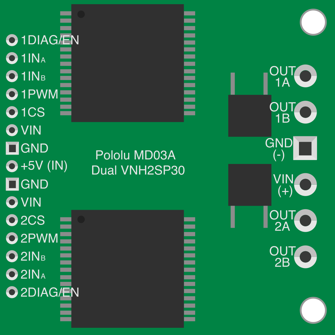
 Design with Pololu MD03A Dual VNH2SP30 Motor Driver in Cirkit Designer
Introduction
The Pololu MD03A Dual VNH2SP30 Motor Driver (Manufacturer Part ID: 708) is a robust and efficient motor driver designed to control two DC motors independently. It is based on the VNH2SP30 full-bridge motor driver ICs, offering high current handling capabilities of up to 30A per channel with built-in thermal protection and current sensing. This makes it an excellent choice for robotics, automation, and other high-power motor control applications.
Explore Projects Built with Pololu MD03A Dual VNH2SP30 Motor Driver
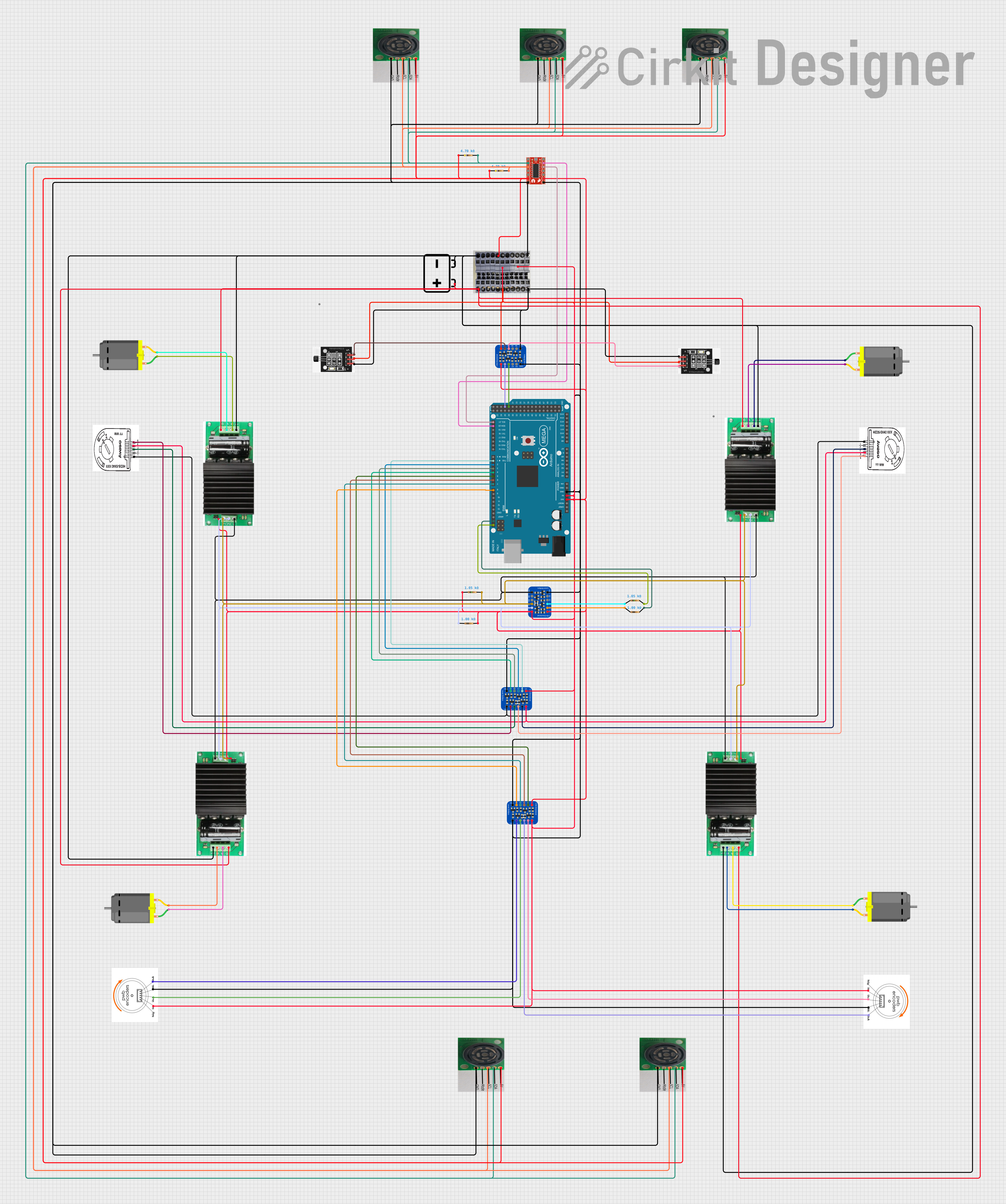 Open Project in Cirkit DesignerOpen Project in Cirkit Designer
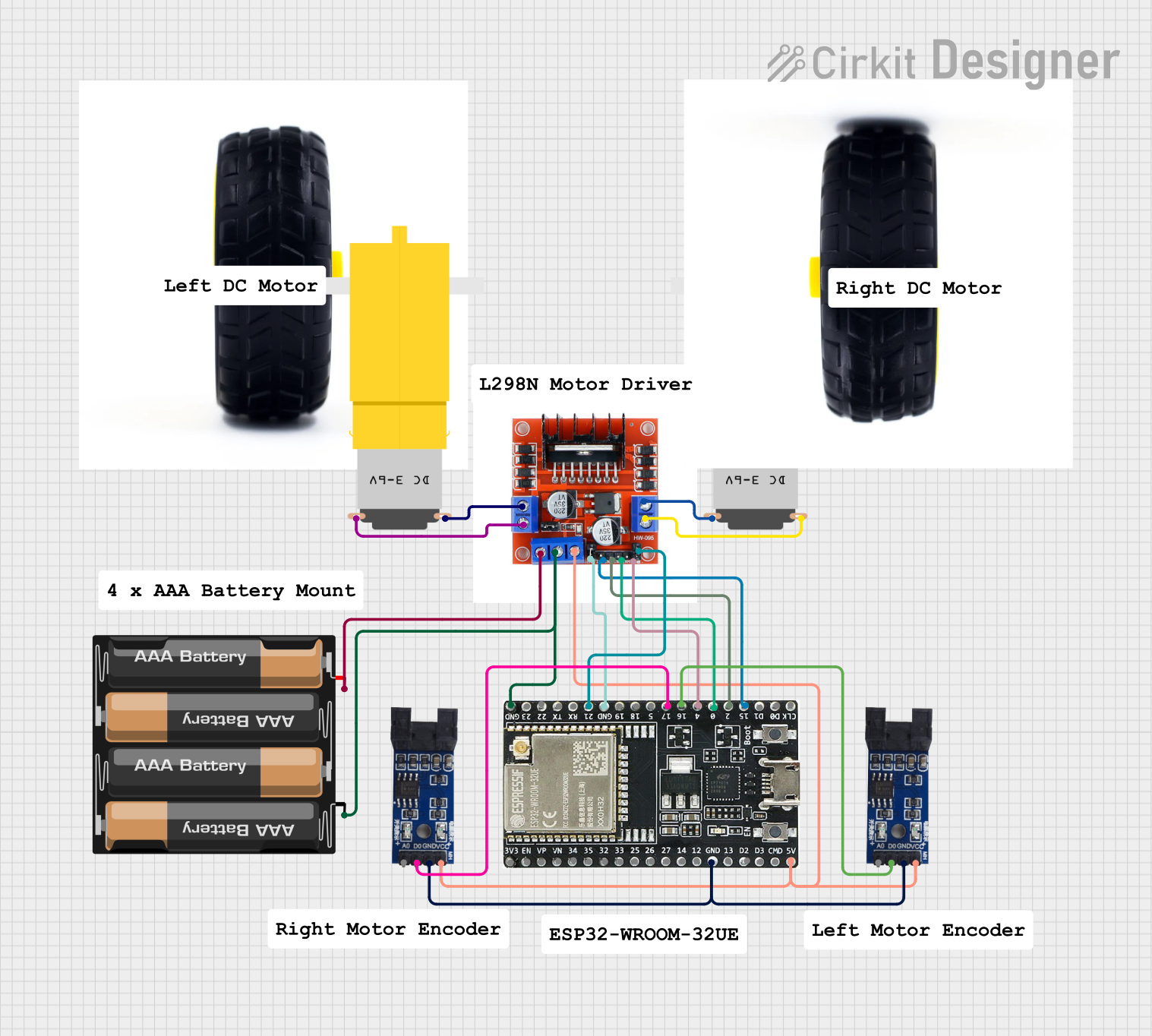 Open Project in Cirkit Designer
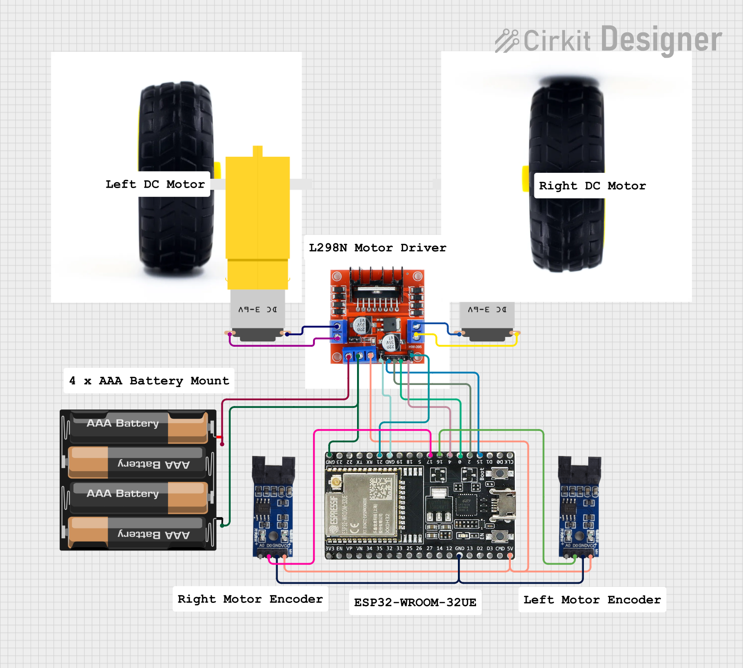 Open Project in Cirkit Designer
Explore Projects Built with Pololu MD03A Dual VNH2SP30 Motor Driver
Open Project in Cirkit DesignerOpen Project in Cirkit DesignerOpen Project in Cirkit DesignerOpen Project in Cirkit DesignerCommon Applications
- Robotics (e.g., driving wheels or tracks)
- Automated guided vehicles (AGVs)
- Conveyor belt systems
- Remote-controlled vehicles
- Industrial automation systems
Technical Specifications
The following table outlines the key technical details of the Pololu MD03A motor driver:
| Parameter | Value |
|---|---|
| Operating Voltage Range | 5.5V to 16V |
| Maximum Continuous Current | 30A per channel |
| Peak Current (short duration) | 60A per channel |
| Logic Voltage | 3.3V or 5V compatible |
| PWM Frequency | Up to 20 kHz |
| Current Sensing | 0.13V/A (approx.) |
| Thermal Shutdown | Yes |
| Reverse Voltage Protection | Yes |
| Dimensions | 1.8" × 1.2" × 0.5" (45 × 30 × 12 mm) |
| Weight | 9.5 g |
Pin Configuration and Descriptions
The Pololu MD03A motor driver has a total of 16 pins. The table below describes each pin:
| Pin Name | Type | Description |
|---|---|---|
| VIN | Power Input | Motor power supply (5.5V to 16V). |
| GND | Power Ground | Ground connection for motor power and logic. |
| VDD | Power Input | Logic voltage input (3.3V or 5V). |
| INA1, INA2 | Logic Input | Motor A direction control inputs. |
| INB1, INB2 | Logic Input | Motor B direction control inputs. |
| PWM A | PWM Input | PWM signal for speed control of Motor A. |
| PWM B | PWM Input | PWM signal for speed control of Motor B. |
| ENA | Logic Input | Enable input for Motor A (active high). |
| ENB | Logic Input | Enable input for Motor B (active high). |
| CS A | Analog Output | Current sense output for Motor A. |
| CS B | Analog Output | Current sense output for Motor B. |
| DIAGA/DIAGB | Digital Output | Diagnostic outputs for Motor A and Motor B (active low on fault). |
| OUTA1, OUTA2 | Motor Output | Outputs for Motor A. |
| OUTB1, OUTB2 | Motor Output | Outputs for Motor B. |
Usage Instructions
How to Use the Component in a Circuit
Power Connections:
- Connect the motor power supply to the VIN pin and ground to the GND pin.
- Ensure the supply voltage is within the range of 5.5V to 16V.
- Connect the logic voltage (3.3V or 5V) to the VDD pin.
Motor Connections:
- Connect the two terminals of Motor A to OUTA1 and OUTA2.
- Connect the two terminals of Motor B to OUTB1 and OUTB2.
Control Signals:
- Use the INA1/INA2 and INB1/INB2 pins to control the direction of Motor A and Motor B, respectively.
- Provide a PWM signal to the PWM A and PWM B pins to control the speed of Motor A and Motor B.
- Enable the motors by setting the ENA and ENB pins high.
Current Sensing:
- Monitor the current draw of Motor A and Motor B using the CS A and CS B pins. The output voltage is proportional to the motor current (approximately 0.13V/A).
Diagnostics:
- Use the DIAGA and DIAGB pins to detect faults such as over-temperature or over-current conditions. These pins go low when a fault is detected.
Important Considerations and Best Practices
- Use a power supply capable of providing sufficient current for your motors.
- Add a capacitor (e.g., 100 µF) across the VIN and GND pins to reduce voltage spikes.
- Ensure proper heat dissipation, especially when operating at high currents.
- Avoid exceeding the maximum voltage and current ratings to prevent damage.
- Use pull-down resistors on unused input pins to avoid floating states.
Example: Connecting to an Arduino UNO
Below is an example Arduino sketch to control two DC motors using the Pololu MD03A motor driver:
// Define motor control pins
#define INA1 2  // Motor A direction control pin 1
#define INA2 3  // Motor A direction control pin 2
#define ENA 9   // Motor A enable (PWM) pin
#define INB1 4  // Motor B direction control pin 1
#define INB2 5  // Motor B direction control pin 2
#define ENB 10  // Motor B enable (PWM) pin

void setup() {
  // Set motor control pins as outputs
  pinMode(INA1, OUTPUT);
  pinMode(INA2, OUTPUT);
  pinMode(ENA, OUTPUT);
  pinMode(INB1, OUTPUT);
  pinMode(INB2, OUTPUT);
  pinMode(ENB, OUTPUT);
}

void loop() {
  // Motor A: Forward at 50% speed
  digitalWrite(INA1, HIGH);
  digitalWrite(INA2, LOW);
  analogWrite(ENA, 128); // PWM value (0-255)

  // Motor B: Reverse at 75% speed
  digitalWrite(INB1, LOW);
  digitalWrite(INB2, HIGH);
  analogWrite(ENB, 192); // PWM value (0-255)

  delay(2000); // Run motors for 2 seconds

  // Stop both motors
  analogWrite(ENA, 0);
  analogWrite(ENB, 0);

  delay(2000); // Wait for 2 seconds
}
Troubleshooting and FAQs
Common Issues
Motors not running:
- Ensure the ENA and ENB pins are set high or receiving a valid PWM signal.
- Verify that the power supply voltage is within the specified range.
Overheating:
- Check for excessive current draw from the motors.
- Ensure proper ventilation or add a heatsink to the motor driver.
Fault indication (DIAGA/DIAGB pins low):
- Check for over-current or over-temperature conditions.
- Reduce the motor load or improve cooling.
Erratic motor behavior:
- Verify that all control signals are properly connected and not floating.
- Add decoupling capacitors to reduce noise.
FAQs
Q: Can I use this motor driver with a 24V motor?
A: No, the maximum operating voltage is 16V. Using a higher voltage may damage the driver.
Q: How do I measure motor current?
A: Connect the CS A or CS B pin to an analog input on your microcontroller. The voltage output is proportional to the motor current (approximately 0.13V/A).
Q: What happens if the motor stalls?
A: The driver has built-in thermal and over-current protection. If a stall causes excessive current, the driver will shut down to prevent damage.
Q: Can I control the motor driver with a Raspberry Pi?
A: Yes, the logic inputs are compatible with 3.3V signals, making it suitable for use with a Raspberry Pi.