How to Use Single Stepper Shield: Examples, Pinouts, and Specs
Introduction
The Single Stepper Shield is an add-on board designed to simplify the control of a single stepper motor in robotics, automation, and other motion control projects. It provides an easy interface between a microcontroller (such as an Arduino) and a stepper motor, enabling precise movement and positioning. The shield integrates essential components like motor driver circuitry, power connections, and control signal pins, making it a convenient solution for stepper motor applications.
Explore Projects Built with Single Stepper Shield
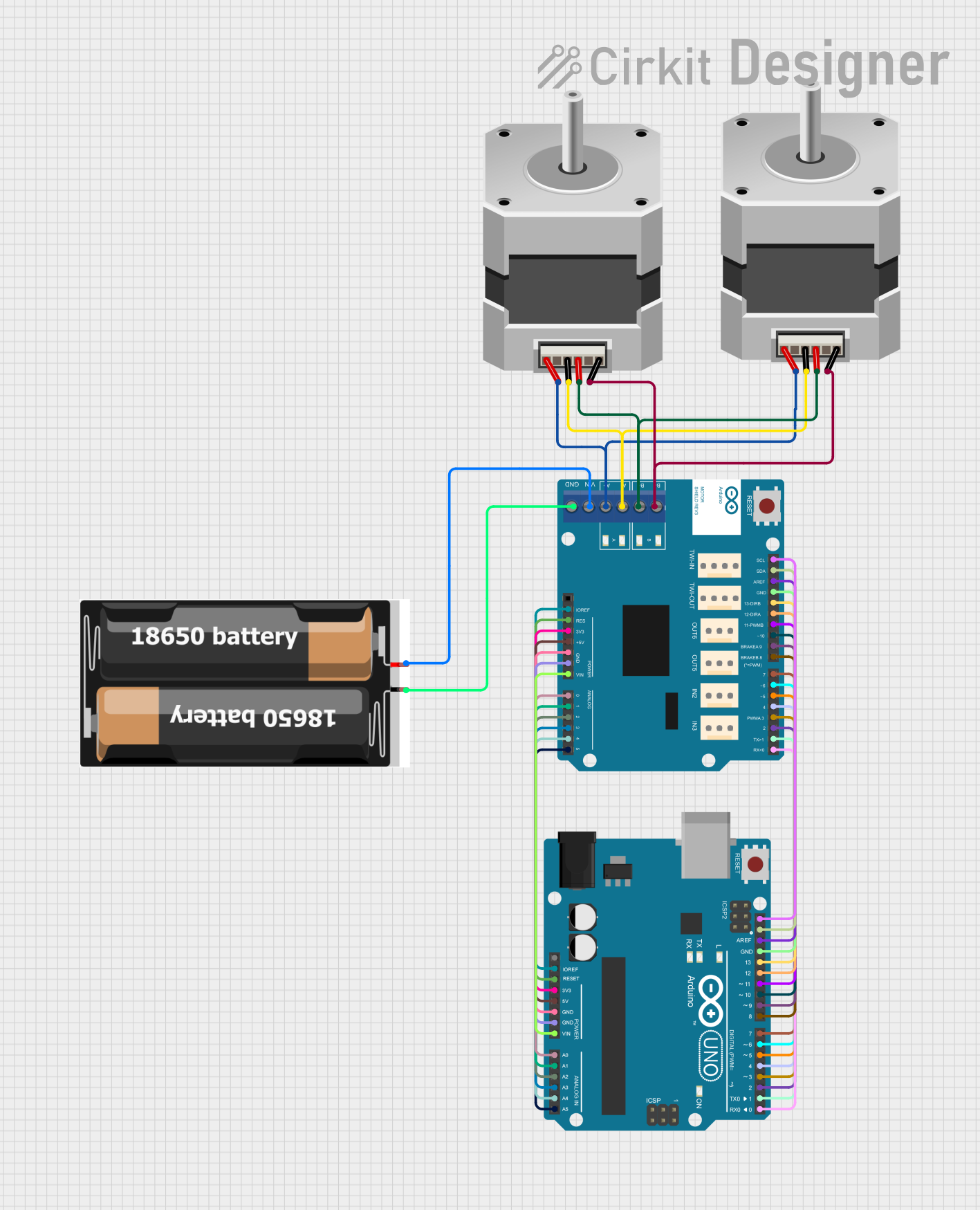
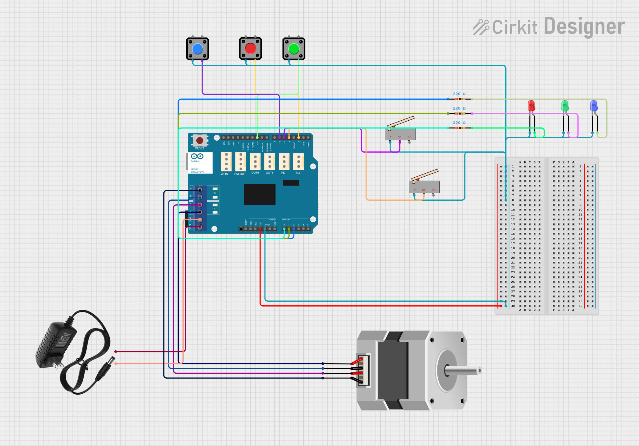
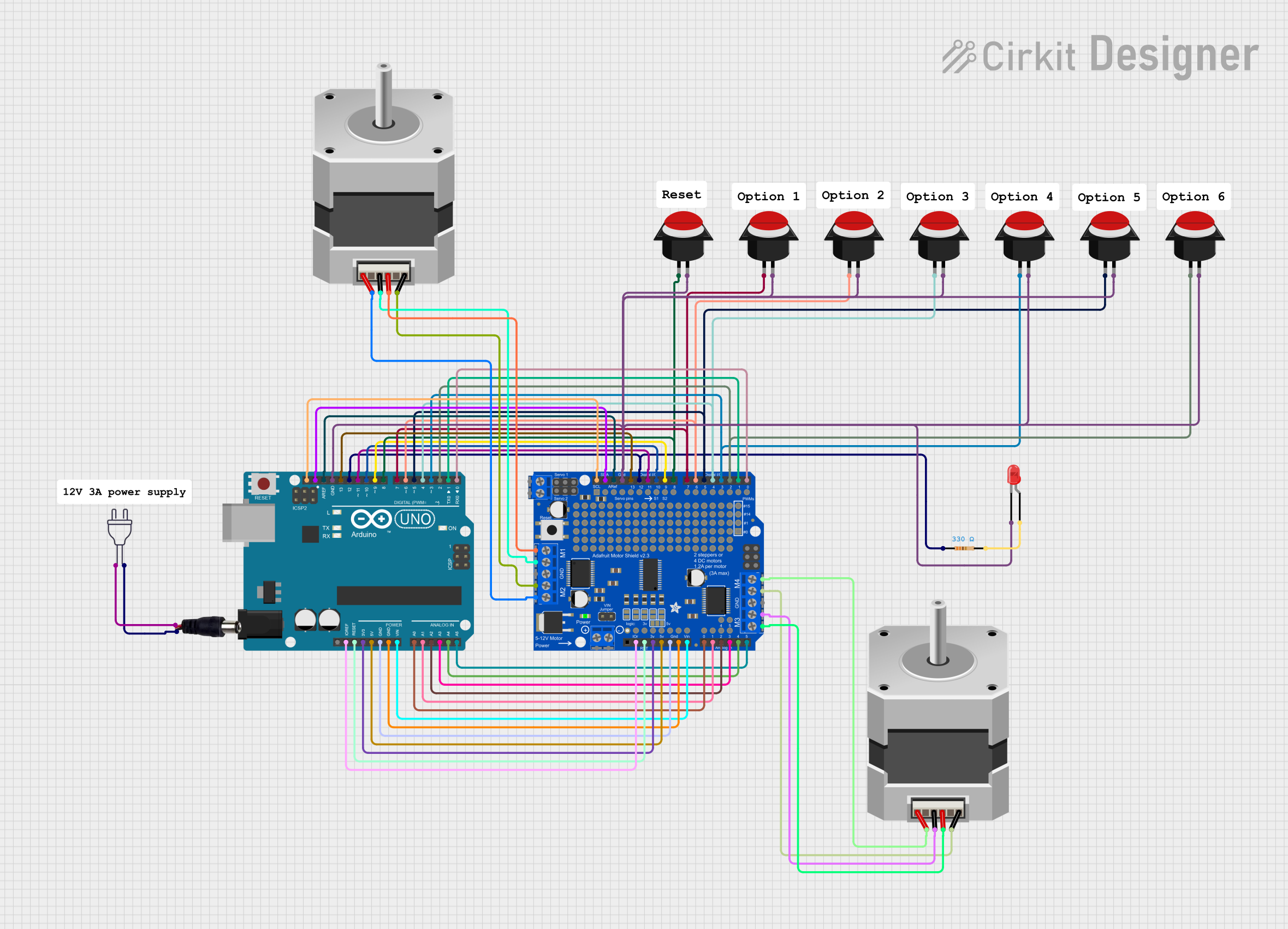

Explore Projects Built with Single Stepper Shield
Common Applications and Use Cases
- Robotics: Controlling robotic arms, wheels, or other moving parts.
- CNC Machines: Driving stepper motors for precise cutting, engraving, or milling.
- 3D Printers: Managing the movement of print heads or build platforms.
- Automation Systems: Controlling conveyor belts, sliders, or other automated mechanisms.
- Educational Projects: Learning about stepper motor control and motion systems.
Technical Specifications
The Single Stepper Shield is designed to work seamlessly with most microcontrollers and stepper motors. Below are its key technical details:
Key Technical Details
- Input Voltage: 6V to 12V DC (motor power supply)
- Logic Voltage: 3.3V or 5V (compatible with most microcontrollers)
- Maximum Motor Current: 2A per phase
- Supported Stepper Motors: Bipolar or unipolar stepper motors
- Microstepping Support: Full-step, half-step, quarter-step, and eighth-step modes
- Control Interface: DIR (direction), STEP (step pulse), ENABLE (motor enable)
- Dimensions: 68mm x 53mm (compatible with Arduino UNO form factor)
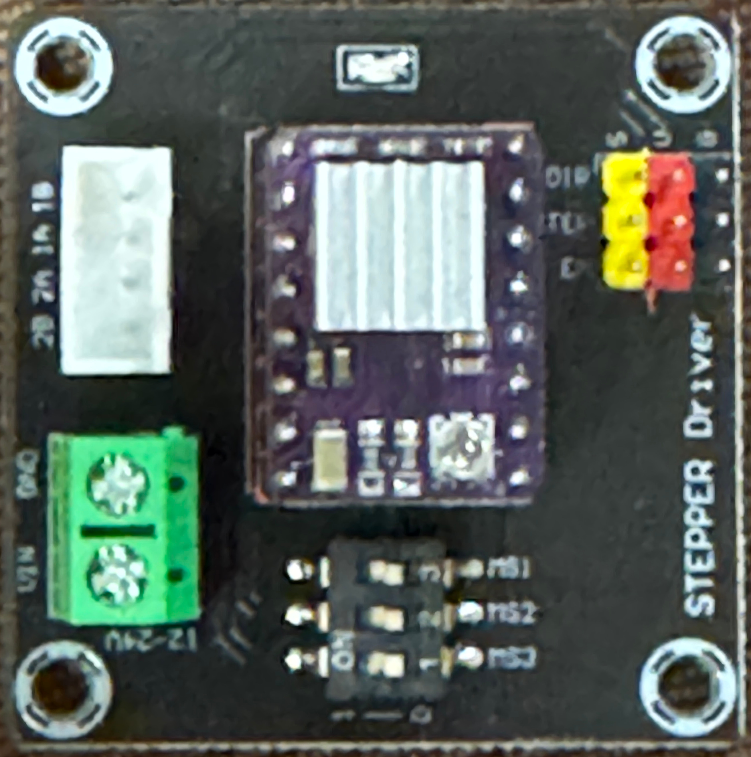
Pin Configuration and Descriptions
The Single Stepper Shield has the following pin layout:
| Pin Name | Type | Description |
|---|---|---|
| VIN | Power Input | Connect to the motor power supply (6V-12V DC). |
| GND | Ground | Common ground for motor and logic circuits. |
| DIR | Control Signal | Sets the direction of motor rotation (HIGH for one direction, LOW for reverse). |
| STEP | Control Signal | Receives step pulses to control motor movement. |
| ENABLE | Control Signal | Enables or disables the motor driver (LOW to enable, HIGH to disable). |
| A+, A- | Motor Output | Connect to one coil of the stepper motor. |
| B+, B- | Motor Output | Connect to the other coil of the stepper motor. |
Usage Instructions
How to Use the Single Stepper Shield in a Circuit
- Mount the Shield: Place the Single Stepper Shield on top of an Arduino UNO or compatible microcontroller board.
- Connect the Stepper Motor: Attach the stepper motor wires to the A+, A-, B+, and B- terminals on the shield. Ensure the wiring matches the motor's datasheet.
- Power the Shield: Connect a DC power supply (6V-12V) to the VIN and GND terminals. Ensure the power supply can provide sufficient current for the motor.
- Control Signals: Use the DIR, STEP, and ENABLE pins to control the motor. These pins can be connected to the Arduino's digital I/O pins.
- Upload Code: Write and upload a program to the Arduino to control the motor's movement.
Important Considerations and Best Practices
- Power Supply: Ensure the power supply voltage matches the motor's requirements. Overvoltage can damage the motor or shield.
- Current Limiting: If the shield supports current limiting, adjust it to match the motor's rated current to prevent overheating.
- Heat Dissipation: The motor driver may generate heat during operation. Use a heatsink or fan if necessary.
- Microstepping: Configure the microstepping mode (if supported) to achieve smoother motor movement.
- Wiring: Double-check all connections before powering the circuit to avoid short circuits or damage.
Example Code for Arduino UNO
Below is an example Arduino sketch to control a stepper motor using the Single Stepper Shield:
// Example code to control a stepper motor using the Single Stepper Shield
// Connect DIR to pin 2, STEP to pin 3, and ENABLE to pin 4 on the Arduino UNO

#define DIR_PIN 2    // Direction control pin
#define STEP_PIN 3   // Step pulse pin
#define ENABLE_PIN 4 // Motor enable pin

void setup() {
  pinMode(DIR_PIN, OUTPUT);    // Set DIR pin as output
  pinMode(STEP_PIN, OUTPUT);   // Set STEP pin as output
  pinMode(ENABLE_PIN, OUTPUT); // Set ENABLE pin as output

  digitalWrite(ENABLE_PIN, LOW); // Enable the motor driver
}

void loop() {
  digitalWrite(DIR_PIN, HIGH); // Set direction to forward
  for (int i = 0; i < 200; i++) { // Move 200 steps (1 revolution for a 1.8° step motor)
    digitalWrite(STEP_PIN, HIGH); // Generate a step pulse
    delayMicroseconds(1000);      // Wait 1ms
    digitalWrite(STEP_PIN, LOW);  // End the step pulse
    delayMicroseconds(1000);      // Wait 1ms
  }

  delay(1000); // Wait 1 second

  digitalWrite(DIR_PIN, LOW); // Set direction to reverse
  for (int i = 0; i < 200; i++) { // Move 200 steps in reverse
    digitalWrite(STEP_PIN, HIGH);
    delayMicroseconds(1000);
    digitalWrite(STEP_PIN, LOW);
    delayMicroseconds(1000);
  }

  delay(1000); // Wait 1 second
}
Troubleshooting and FAQs
Common Issues and Solutions
Motor Not Moving:
- Check the power supply voltage and current. Ensure it matches the motor's requirements.
- Verify the motor wiring. Ensure the coils are connected to the correct terminals (A+, A-, B+, B-).
- Ensure the ENABLE pin is set to LOW to activate the motor driver.
Motor Vibrates but Doesn't Rotate:
- Check the DIR and STEP signal connections. Ensure the Arduino is sending proper pulses.
- Verify the motor's coil connections. Incorrect wiring can cause erratic behavior.
Motor Overheating:
- Reduce the current limit on the shield (if adjustable).
- Ensure the motor is not stalled or overloaded.
Driver Overheating:
- Add a heatsink or fan to the motor driver chip.
- Reduce the motor's current draw by adjusting the current limit.
FAQs
Q: Can I use this shield with a unipolar stepper motor?
A: Yes, but you need to connect only the four coil wires (ignore the center tap wires).
Q: What microcontrollers are compatible with this shield?
A: The shield is compatible with most 3.3V and 5V microcontrollers, including Arduino UNO, Mega, and similar boards.
Q: How do I adjust the microstepping mode?
A: Refer to the shield's documentation or onboard jumpers to configure the microstepping mode.
Q: Can I control the motor speed?
A: Yes, by adjusting the delay between STEP pulses in your code, you can control the motor's speed.