Cirkit Designer Logo
Cirkit Designer
Your all-in-one circuit design IDE
Home / 
Component Documentation

How to Use 12V to 5V Buck Converter: Examples, Pinouts, and Specs

Image of 12V to 5V Buck Converter
Cirkit Designer LogoDesign with 12V to 5V Buck Converter in Cirkit Designer

Introduction

The 12V to 5V Buck Converter is a DC-DC step-down voltage regulator designed to efficiently convert a 12V input voltage to a stable 5V output. This component is widely used in power supply applications where a lower voltage is required to power devices such as microcontrollers, sensors, and USB-powered peripherals. Its high efficiency and compact design make it ideal for battery-powered systems, automotive electronics, and embedded systems.

Explore Projects Built with 12V to 5V Buck Converter

Use Cirkit Designer to design, explore, and prototype these projects online. Some projects support real-time simulation. Click "Open Project" to start designing instantly!
Battery-Powered DC Generator with XL4015 Buck Converter
Image of conveyor: A project utilizing 12V to 5V Buck Converter in a practical application
This circuit consists of a 12V battery connected to a rocker switch, which controls the input to an XL4015 DC Buck Step-down converter. The converter steps down the voltage to power a DC generator, with the generator's output connected back to the converter to form a feedback loop.
Cirkit Designer LogoOpen Project in Cirkit Designer
USB Power Supply with Overcurrent Protection
Image of USB Charging port: A project utilizing 12V to 5V Buck Converter in a practical application
This circuit is designed to step down voltage from a 12V battery to a lower voltage suitable for USB devices. It includes a buck converter connected to the battery through a fuse and fuse holder for overcurrent protection. The output of the buck converter is connected to a USB female port, providing a regulated power supply for USB-powered devices.
Cirkit Designer LogoOpen Project in Cirkit Designer
Dual Motor Control Circuit with Directional Switching and Voltage Regulation
Image of Pencuci Kipas: A project utilizing 12V to 5V Buck Converter in a practical application
This circuit features a 12V battery connected through a rocker switch to two buck converters, one of which steps down the voltage to power two DC mini metal gear motors, and the other is connected to a directional switch that controls a third DC mini metal gear motor. The XL4015 5A DC Buck Step-down converter's output is connected to two motors, allowing them to run at a reduced voltage, while the other buck converter's output is routed through a directional switch to control the direction of the third motor.
Cirkit Designer LogoOpen Project in Cirkit Designer
Battery-Powered DC-DC Converter System for Multi-Voltage Power Distribution
Image of test 1 ih: A project utilizing 12V to 5V Buck Converter in a practical application
This circuit converts a 38.5V battery output to multiple lower voltage levels using a series of DC-DC converters and a power module. It includes an emergency stop switch for safety and distributes power to various components such as a relay module, USB ports, and a bus servo adaptor.
Cirkit Designer LogoOpen Project in Cirkit Designer

Explore Projects Built with 12V to 5V Buck Converter

Use Cirkit Designer to design, explore, and prototype these projects online. Some projects support real-time simulation. Click "Open Project" to start designing instantly!
Image of conveyor: A project utilizing 12V to 5V Buck Converter in a practical application
Battery-Powered DC Generator with XL4015 Buck Converter
This circuit consists of a 12V battery connected to a rocker switch, which controls the input to an XL4015 DC Buck Step-down converter. The converter steps down the voltage to power a DC generator, with the generator's output connected back to the converter to form a feedback loop.
Cirkit Designer LogoOpen Project in Cirkit Designer
Image of USB Charging port: A project utilizing 12V to 5V Buck Converter in a practical application
USB Power Supply with Overcurrent Protection
This circuit is designed to step down voltage from a 12V battery to a lower voltage suitable for USB devices. It includes a buck converter connected to the battery through a fuse and fuse holder for overcurrent protection. The output of the buck converter is connected to a USB female port, providing a regulated power supply for USB-powered devices.
Cirkit Designer LogoOpen Project in Cirkit Designer
Image of Pencuci Kipas: A project utilizing 12V to 5V Buck Converter in a practical application
Dual Motor Control Circuit with Directional Switching and Voltage Regulation
This circuit features a 12V battery connected through a rocker switch to two buck converters, one of which steps down the voltage to power two DC mini metal gear motors, and the other is connected to a directional switch that controls a third DC mini metal gear motor. The XL4015 5A DC Buck Step-down converter's output is connected to two motors, allowing them to run at a reduced voltage, while the other buck converter's output is routed through a directional switch to control the direction of the third motor.
Cirkit Designer LogoOpen Project in Cirkit Designer
Image of test 1 ih: A project utilizing 12V to 5V Buck Converter in a practical application
Battery-Powered DC-DC Converter System for Multi-Voltage Power Distribution
This circuit converts a 38.5V battery output to multiple lower voltage levels using a series of DC-DC converters and a power module. It includes an emergency stop switch for safety and distributes power to various components such as a relay module, USB ports, and a bus servo adaptor.
Cirkit Designer LogoOpen Project in Cirkit Designer

Common Applications:

  • Powering microcontrollers (e.g., Arduino, Raspberry Pi)
  • USB device power supplies
  • Automotive electronics
  • Battery-powered systems
  • LED lighting systems

Technical Specifications

Below are the key technical details of the 12V to 5V Buck Converter:

Parameter Value
Input Voltage Range 7V to 24V
Output Voltage 5V ± 0.1V
Maximum Output Current 3A (typical), 2A (continuous load)
Efficiency Up to 95%
Switching Frequency 150 kHz
Operating Temperature -40°C to +85°C
Dimensions Varies (e.g., 22mm x 17mm x 4mm)

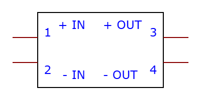
Pin Configuration and Descriptions

The 12V to 5V Buck Converter typically has the following pin configuration:

Pin Name Description
VIN Input voltage pin (connect to 12V power source)
GND Ground pin (common ground for input and output)
VOUT Output voltage pin (provides regulated 5V output)

Usage Instructions

How to Use the Component in a Circuit

  1. Connect the Input Voltage:

    • Connect the VIN pin to a 12V DC power source. Ensure the input voltage is within the specified range (7V to 24V).
    • Connect the GND pin to the ground of the power source.
  2. Connect the Output Load:

    • Connect the VOUT pin to the device or circuit requiring 5V power.
    • Connect the GND pin to the ground of the load.
  3. Verify Connections:

    • Double-check all connections to ensure proper polarity and avoid short circuits.
  4. Power On:

    • Turn on the 12V power source. The buck converter will regulate the input voltage and provide a stable 5V output.

Important Considerations and Best Practices

  • Heat Dissipation: For high current loads (e.g., >1.5A), ensure proper heat dissipation by using a heatsink or providing adequate ventilation.
  • Input Voltage Range: Do not exceed the maximum input voltage (24V) to avoid damaging the converter.
  • Output Filtering: If the output voltage has noise, consider adding a capacitor (e.g., 100µF) across the VOUT and GND pins for additional filtering.
  • Load Current: Ensure the load does not exceed the maximum continuous current rating (2A) to prevent overheating or damage.

Example: Using with an Arduino UNO

The 12V to 5V Buck Converter can be used to power an Arduino UNO from a 12V power source. Below is an example circuit and Arduino code:

Circuit Connections:

  • Connect the VIN pin of the buck converter to a 12V DC power source.
  • Connect the GND pin of the buck converter to the ground of the power source.
  • Connect the VOUT pin of the buck converter to the 5V pin of the Arduino UNO.
  • Connect the GND pin of the buck converter to the GND pin of the Arduino UNO.

Arduino Code:

// Example code to blink an LED connected to pin 13 of the Arduino UNO
// Ensure the Arduino is powered via the 5V output of the buck converter

void setup() {
  pinMode(13, OUTPUT); // Set pin 13 as an output
}

void loop() {
  digitalWrite(13, HIGH); // Turn the LED on
  delay(1000);            // Wait for 1 second
  digitalWrite(13, LOW);  // Turn the LED off
  delay(1000);            // Wait for 1 second
}

Troubleshooting and FAQs

Common Issues and Solutions

  1. No Output Voltage:

    • Cause: Incorrect wiring or insufficient input voltage.
    • Solution: Verify that the VIN and GND pins are correctly connected to the power source and that the input voltage is within the specified range.
  2. Overheating:

    • Cause: Excessive load current or poor ventilation.
    • Solution: Reduce the load current or add a heatsink to the converter.
  3. Output Voltage Fluctuations:

    • Cause: Insufficient input power or high-frequency noise.
    • Solution: Add a capacitor (e.g., 100µF) across the input and/or output pins to stabilize the voltage.
  4. Damaged Converter:

    • Cause: Input voltage exceeded the maximum rating or reverse polarity connection.
    • Solution: Replace the converter and ensure proper input voltage and polarity in future use.

FAQs

Q: Can I use the buck converter to power a Raspberry Pi?
A: Yes, but ensure the converter can supply sufficient current (at least 2.5A) for the Raspberry Pi model you are using.

Q: Can I use this converter with a 24V input?
A: Yes, as long as the input voltage does not exceed 24V and the load current is within the specified range.

Q: Is the output voltage adjustable?
A: Most 12V to 5V buck converters provide a fixed 5V output. If you need an adjustable output, look for a model with a potentiometer for voltage adjustment.

Q: Can I use this converter for audio applications?
A: Yes, but you may need additional filtering capacitors to reduce noise for sensitive audio circuits.