How to Use ATS 1 Phase: Examples, Pinouts, and Specs
Introduction
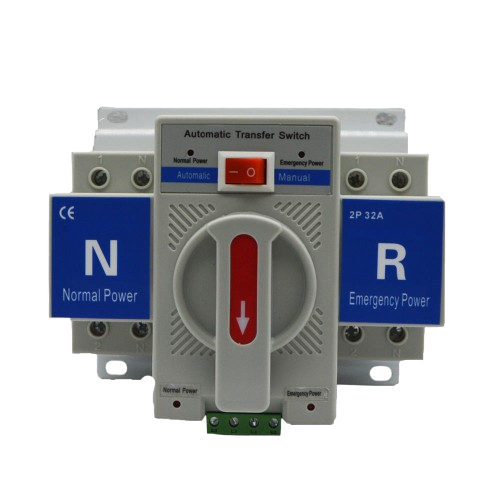
The ATS 1 Phase is an Automatic Transfer Switch designed for single-phase electrical systems. It ensures uninterrupted power supply by automatically switching between a primary power source (e.g., utility grid) and a backup power source (e.g., generator or inverter) during power outages or fluctuations. This component is widely used in residential, commercial, and industrial applications where continuous power is critical.
Explore Projects Built with ATS 1 Phase


Explore Projects Built with ATS 1 Phase
Common Applications and Use Cases
- Residential homes with backup generators or inverters
- Small businesses requiring uninterrupted power for critical equipment
- Industrial systems with single-phase backup power setups
- Data centers and IT infrastructure for maintaining uptime
- Medical equipment and emergency systems
Technical Specifications
The ATS 1 Phase is designed to handle single-phase power systems with the following specifications:
Key Technical Details
| Parameter | Value |
|---|---|
| Operating Voltage Range | 110V AC to 240V AC |
| Maximum Current Rating | 63A |
| Frequency | 50Hz / 60Hz |
| Switching Time | ≤ 10ms |
| Control Voltage | 12V DC or 24V DC (depending on model) |
| Operating Temperature | -20°C to 55°C |
| Enclosure Protection | IP30 (indoor use) |
| Dimensions | 200mm x 150mm x 100mm |
| Weight | 1.5kg |
Pin Configuration and Descriptions
The ATS 1 Phase has terminal connections for both the primary and backup power sources, as well as load output. Below is the pin configuration:
| Terminal Label | Description |
|---|---|
| L1 (Primary) | Live input from the primary power source |
| N1 (Primary) | Neutral input from the primary power source |
| L2 (Backup) | Live input from the backup power source |
| N2 (Backup) | Neutral input from the backup power source |
| L (Load) | Live output to the load |
| N (Load) | Neutral output to the load |
| GND | Ground connection for safety |
Usage Instructions
How to Use the ATS 1 Phase in a Circuit
Power Source Connections:
- Connect the live (L1) and neutral (N1) terminals to the primary power source (e.g., utility grid).
- Connect the live (L2) and neutral (N2) terminals to the backup power source (e.g., generator or inverter).
Load Connection:
- Connect the live (L) and neutral (N) terminals to the load (e.g., appliances, equipment).
Grounding:
- Ensure the GND terminal is properly connected to the system ground for safety.
Control Voltage:
- Provide the required control voltage (12V DC or 24V DC) to the ATS control circuit as specified in the model.
Testing:
- Test the ATS by simulating a power outage on the primary source. Verify that the switch transfers to the backup source and returns to the primary source when power is restored.
Important Considerations and Best Practices
- Ensure the ATS is installed by a qualified electrician to comply with local electrical codes.
- Verify that the current and voltage ratings of the ATS match the system requirements.
- Use proper circuit breakers or fuses to protect the ATS and connected equipment.
- Regularly inspect and maintain the ATS to ensure reliable operation.
- Avoid exposing the ATS to moisture or extreme temperatures beyond its operating range.
Example: Connecting ATS 1 Phase to an Arduino UNO
The ATS 1 Phase can be monitored using an Arduino UNO to detect the active power source. Below is an example code snippet:
// Example code to monitor ATS status using Arduino UNO
// Connect ATS status output pins to Arduino digital pins 2 and 3

const int primaryStatusPin = 2; // Pin connected to primary source status
const int backupStatusPin = 3;  // Pin connected to backup source status

void setup() {
  pinMode(primaryStatusPin, INPUT); // Set primary status pin as input
  pinMode(backupStatusPin, INPUT);  // Set backup status pin as input
  Serial.begin(9600);              // Initialize serial communication
}

void loop() {
  int primaryStatus = digitalRead(primaryStatusPin); // Read primary status
  int backupStatus = digitalRead(backupStatusPin);   // Read backup status

  if (primaryStatus == HIGH) {
    Serial.println("Primary power source is active.");
  } else if (backupStatus == HIGH) {
    Serial.println("Backup power source is active.");
  } else {
    Serial.println("No power source is active.");
  }

  delay(1000); // Wait for 1 second before next reading
}
Troubleshooting and FAQs
Common Issues and Solutions
ATS Does Not Switch to Backup Power:
- Cause: Backup power source is not properly connected or not operational.
- Solution: Verify the backup power source connections and ensure it is functioning.
Frequent Switching Between Sources:
- Cause: Unstable primary power supply or incorrect voltage settings.
- Solution: Check the primary power source for stability and ensure the ATS voltage range matches the system.
No Output to Load:
- Cause: Loose connections or blown fuses.
- Solution: Inspect all connections and replace any blown fuses.
Control Circuit Not Responding:
- Cause: Incorrect control voltage or damaged control circuit.
- Solution: Verify the control voltage and inspect the control circuit for damage.
FAQs
Q1: Can the ATS 1 Phase be used outdoors?
A1: No, the ATS 1 Phase is rated for indoor use only (IP30). Use an enclosure for outdoor installations.
Q2: What happens if both power sources fail?
A2: The ATS will not provide output to the load if both sources are unavailable. Consider adding a UPS for critical systems.
Q3: Can the ATS handle three-phase systems?
A3: No, the ATS 1 Phase is specifically designed for single-phase systems. Use a three-phase ATS for such applications.
Q4: How often should the ATS be maintained?
A4: It is recommended to inspect and maintain the ATS every 6 to 12 months to ensure reliable operation.