
How to Use AC CIRUIT BREAKER: Examples, Pinouts, and Specs
 Design with AC CIRUIT BREAKER in Cirkit Designer
Introduction
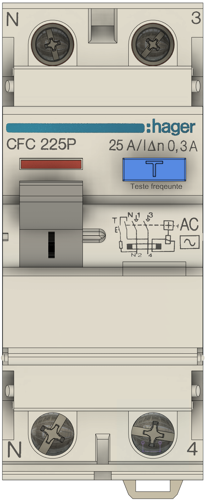
An AC Circuit Breaker is a safety device designed to automatically interrupt the flow of electrical current in an alternating current (AC) circuit. It protects electrical systems from damage caused by overloads, short circuits, or other faults by breaking the circuit when abnormal conditions are detected. Unlike fuses, circuit breakers can be reset and reused after tripping.
Explore Projects Built with AC CIRUIT BREAKER
 Open Project in Cirkit Designer
 Open Project in Cirkit Designer
 Open Project in Cirkit Designer
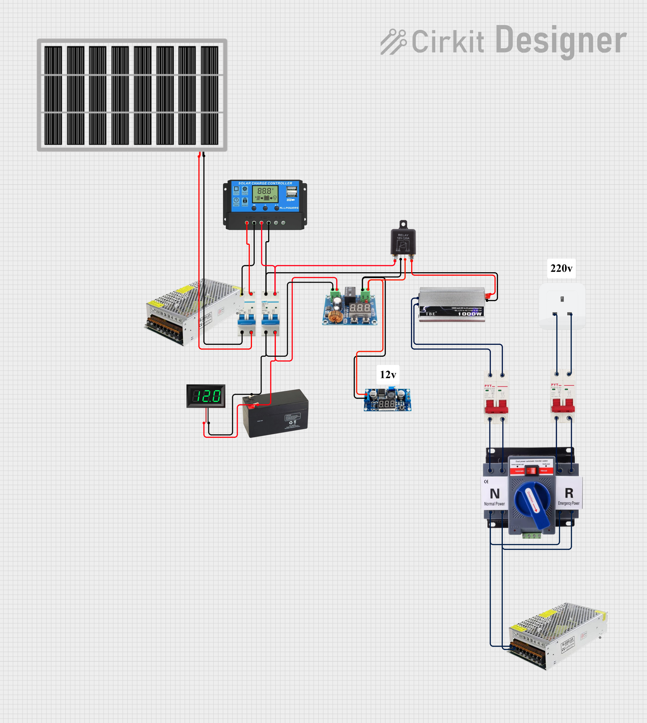 Open Project in Cirkit Designer
Explore Projects Built with AC CIRUIT BREAKER
Open Project in Cirkit DesignerOpen Project in Cirkit DesignerOpen Project in Cirkit DesignerOpen Project in Cirkit DesignerCommon Applications and Use Cases
- Residential and commercial electrical panels for circuit protection.
- Industrial machinery and equipment to prevent electrical damage.
- Power distribution systems in buildings and factories.
- Protection of sensitive electronic devices from power surges and faults.
Technical Specifications
Below are the key technical details of a typical AC Circuit Breaker:
| Parameter | Specification |
|---|---|
| Rated Voltage | 120V AC, 240V AC, or higher |
| Rated Current | 10A, 16A, 20A, 32A, 50A, etc. |
| Breaking Capacity | 6kA, 10kA, or higher |
| Frequency | 50Hz / 60Hz |
| Trip Mechanism | Thermal-magnetic or electronic |
| Number of Poles | 1P, 2P, 3P, or 4P |
| Operating Temperature | -20°C to 70°C |
| Mounting Type | DIN rail or panel-mounted |
| Reset Mechanism | Manual reset |
Pin Configuration and Descriptions
AC Circuit Breakers do not have traditional pins like electronic components but instead feature terminals for wiring. Below is a description of the terminals:
| Terminal | Description |
|---|---|
| Line (Input) | Connects to the incoming AC power supply. |
| Load (Output) | Connects to the load or downstream circuit. |
| Ground | Optional terminal for grounding (if applicable). |
Usage Instructions
How to Use the Component in a Circuit
- Determine the Specifications: Select an AC Circuit Breaker with a rated voltage and current suitable for your application. Ensure the breaking capacity is sufficient for the maximum fault current in your system.
- Wiring:
- Connect the Line (Input) terminal to the incoming AC power supply.
- Connect the Load (Output) terminal to the downstream circuit or device.
- If applicable, connect the Ground terminal to the grounding system.
- Mounting: Install the circuit breaker on a DIN rail or secure it to a panel using screws, depending on the mounting type.
- Testing: After installation, test the circuit breaker by manually tripping it and resetting it to ensure proper operation.
Important Considerations and Best Practices
- Always turn off the main power supply before installing or servicing the circuit breaker.
- Use appropriately rated wires and connectors to prevent overheating or damage.
- Ensure the circuit breaker is installed in a well-ventilated area to avoid overheating.
- Periodically inspect the circuit breaker for signs of wear, damage, or corrosion.
- For sensitive or critical applications, consider using a circuit breaker with an electronic trip mechanism for precise protection.
Example: Connecting to an Arduino UNO
While AC Circuit Breakers are not directly connected to microcontrollers like the Arduino UNO, they can be used in conjunction with relays or sensors to monitor and control AC circuits. Below is an example of how to monitor the state of a circuit breaker using an Arduino and a current sensor:
/*
  Example: Monitoring an AC Circuit Breaker with Arduino
  This code reads the current sensor output to detect if the circuit breaker
  is supplying power to the load. If no current is detected, it assumes the
  breaker has tripped.
*/

const int sensorPin = A0;  // Analog pin connected to the current sensor
const int threshold = 100; // Threshold value for current detection

void setup() {
  Serial.begin(9600); // Initialize serial communication
  pinMode(sensorPin, INPUT); // Set the sensor pin as input
}

void loop() {
  int sensorValue = analogRead(sensorPin); // Read the sensor value

  if (sensorValue < threshold) {
    // If the sensor value is below the threshold, the breaker may be tripped
    Serial.println("Circuit breaker is OFF or tripped!");
  } else {
    // If the sensor value is above the threshold, the breaker is ON
    Serial.println("Circuit breaker is ON.");
  }

  delay(1000); // Wait for 1 second before the next reading
}
Troubleshooting and FAQs
Common Issues Users Might Face
Circuit Breaker Trips Frequently:
- Cause: Overloaded circuit or short circuit.
- Solution: Reduce the load on the circuit or check for wiring faults.
Circuit Breaker Does Not Trip During a Fault:
- Cause: Faulty or incorrectly rated circuit breaker.
- Solution: Replace the circuit breaker with one that matches the system's requirements.
Circuit Breaker Overheats:
- Cause: Loose connections or undersized wires.
- Solution: Tighten all connections and use wires with appropriate current ratings.
Cannot Reset the Circuit Breaker:
- Cause: Persistent fault in the circuit.
- Solution: Identify and fix the fault before attempting to reset the breaker.
Solutions and Tips for Troubleshooting
- Use a multimeter to check for continuity and voltage levels in the circuit.
- Inspect the breaker for physical damage, such as cracks or burn marks.
- Ensure the breaker is installed in the correct orientation (Line and Load terminals).
- Consult the manufacturer's documentation for specific troubleshooting steps.
By following this documentation, users can safely and effectively use an AC Circuit Breaker to protect their electrical systems.